EFCO S5600 Structural Glazed User Manual
Page 11
EFCO CORPORATION 7/2012 PART NO. Y306
Page 11 of 28
Series 5600 Silicone Structural Glazed Installation Instructions
PRESSURE
PLATE SCREW
P
R
E
S
S
U
R
E
PL
AT
E LEN
G
TH
M
U
LLI
ON LENGT
H
COVER LENGTH
2"
2"
PR
ESSURE
PLATE
LENGT
H
MULLION L
E
NGTH
COVER LEN
G
TH
1/2"
1 "
1
/2
"
1/
2
"
4"
3" M
IN
.
2"
1" MIN.
4 1
/2"
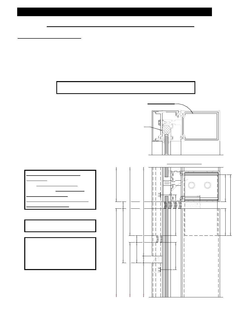
Section V: Vertical Jamb Splice Joints
Vertical Jamb Splice Joints
A.)
Splice joints should occur at spandrel areas. Mullion splice joints for this system are
not designed to compensate for varying floor levels. (Reference “APPROVED” shop
drawings for allowable adjustment, i.e., anchors.)
B.)
Splice joint width should be based on sealant movement capabilities and the
following formula.
C.)
Where head clearance is
insufficient to allow top mullions
to be lifted over sleeve. A
retractable sleeve will be used.
The sleeve is taped into top
mullion and dropped to stop
screw in mullion below.
D.)
Do not match drill anchors until a
check of expansion joints and
wall installation is made.
Note: All anchors must be fixed
before glazing begins.
Note: When mull splice is shop
installed into lower
mullion, shear block
screws will be used in
standard locations, as
shown dotted.
Mullion splice
sleeve with
bond breaker
tape.
Field install
backer rod at
pressure plate
joint to back
up sealant.
Slip-in Horizontal
Linear expansion for aluminum, in inches =
[Length] X [F degrees difference in temperature] X [.0000129]
Note: SSG Vertical Splice
Locations EFCO recommends
that Vertical Splice Line should
be below the Intermediate
Horizontal Member, this will
Minimize Shear Stress at the
Structural Seal Line.