Sleeve anchors) – EFCO S5500 Advanced User Manual
Page 7
EFCO CORPORATION 6/2012 PART NO. Y557
7
Series 5500 Advanced & Alternate Installation Instructions
Section III: Alternate Head Anchorage Method
(Sleeve Anchors)
STEP #1 (Outside Glazed) INSTALL FRAME COMPONENTS
A. Refer to the approved shop drawings for job specific conditions, anchor type, anchor
bolt sizes, and locations. Install assemblies according to the approved shop drawings.
The anchor type used must be selected based on the structural requirements and the
substrate.
B. Follow steps 2 through 5 in Section III of the
Standard Installation Instructions
to
complete the installation.
C. Refer to Sections IV and V of the
Standard Installation Instructions
for Glazing
Preparation and Glazing Installation.
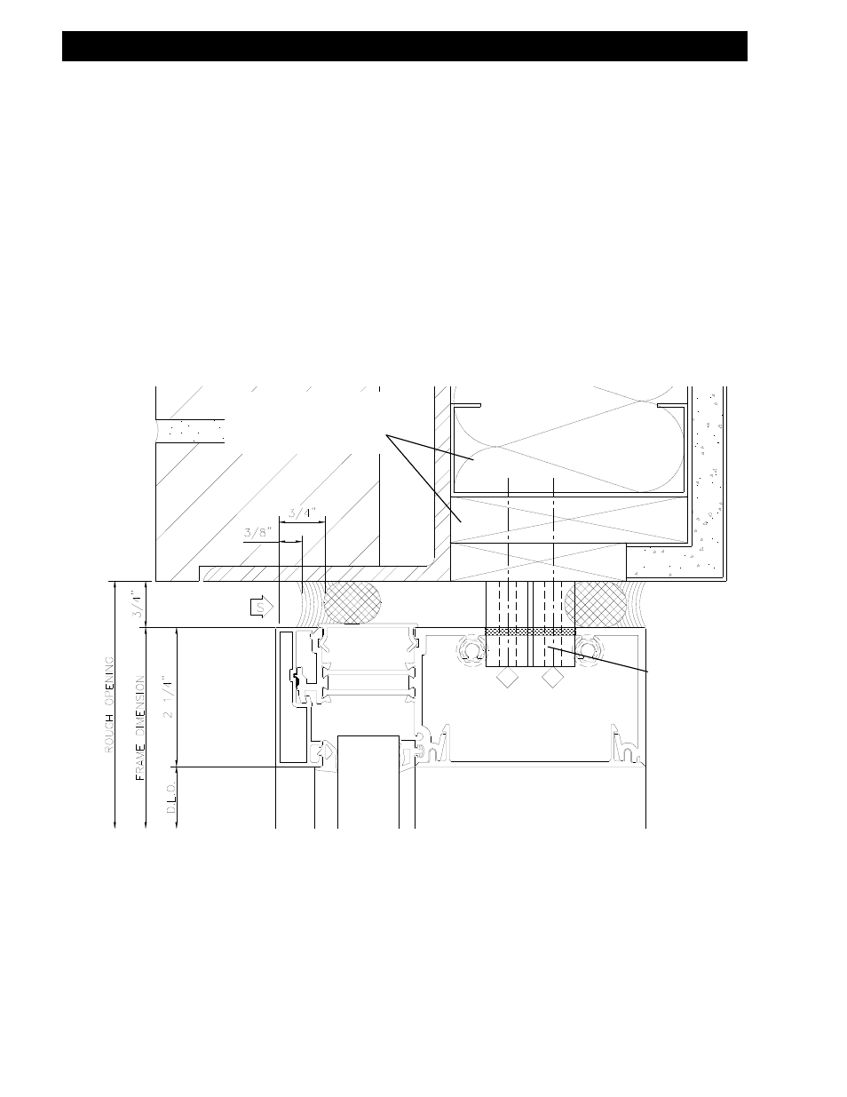
ANCHORAGE DETAIL FOR HEAD CONDITIONS
ATTACHING TO WOOD OR LIGHT GAUGE METAL STUDS
ANCHOR BOLTS AND
SLEEVE (Type and
quantity as required by
conditions and loads.
See Shop Drawings.)
LIGHT GAUGE
METAL STUDS OR
WOOD SUBSTRATE
Note: It is up to the responsible engineer to determine
the structural adequacy and type of anchorage method
to be used for a given substrate, applied loads, and
building movements. The S-5500 has different
anchorage options available to meet these conditions.