EFCO S5500 Advanced User Manual
Page 24
EFCO CORPORATION 6/2012 PART NO. Y557
24
Series 5500 Advanced & Alternate Installation Instructions
Section V: Vertical Splice Joints
STEP #1 LOCATE SPLICE JOINTS
A. Splice joints should occur at spandrel areas (if possible). Refer to the approved shop
drawings for actual locations.
B. Depending on job requirements, the mullion splice may be shop or field assembled in
the top of the lower mullion. The cover splice is attached to the bottom of the upper
mullion. Where head clearance is insufficient to allow the top mullion to be lifted over
the splice sleeves, retractable splices should be used. The splices are to be taped into
the bottom of the top mullion and dropped down to the stop screw in the mullion
below.
C. GENERAL NOTE: The following pages depict a splice joint of 1/2”. This will allow plus
or minus 1/4” of movement for each splice location. Thermal expansion and live
deflection requirements should be considered when determining the location and
quantities of splice joints. If the total amount of movement cannot be accommodated
locating splices at every other floor or alternatively at each floor, expansion
horizontals or some alternative method should be used. Contact EFCO for further
evaluation.
D. Refer to this section for pressure cover splice locations, mullion splice locations, and
sealing instructions.
E. Once a final check of expansion joint placement and mullion position is made, the final
match drilling of mullion through anchor holes may be completed.
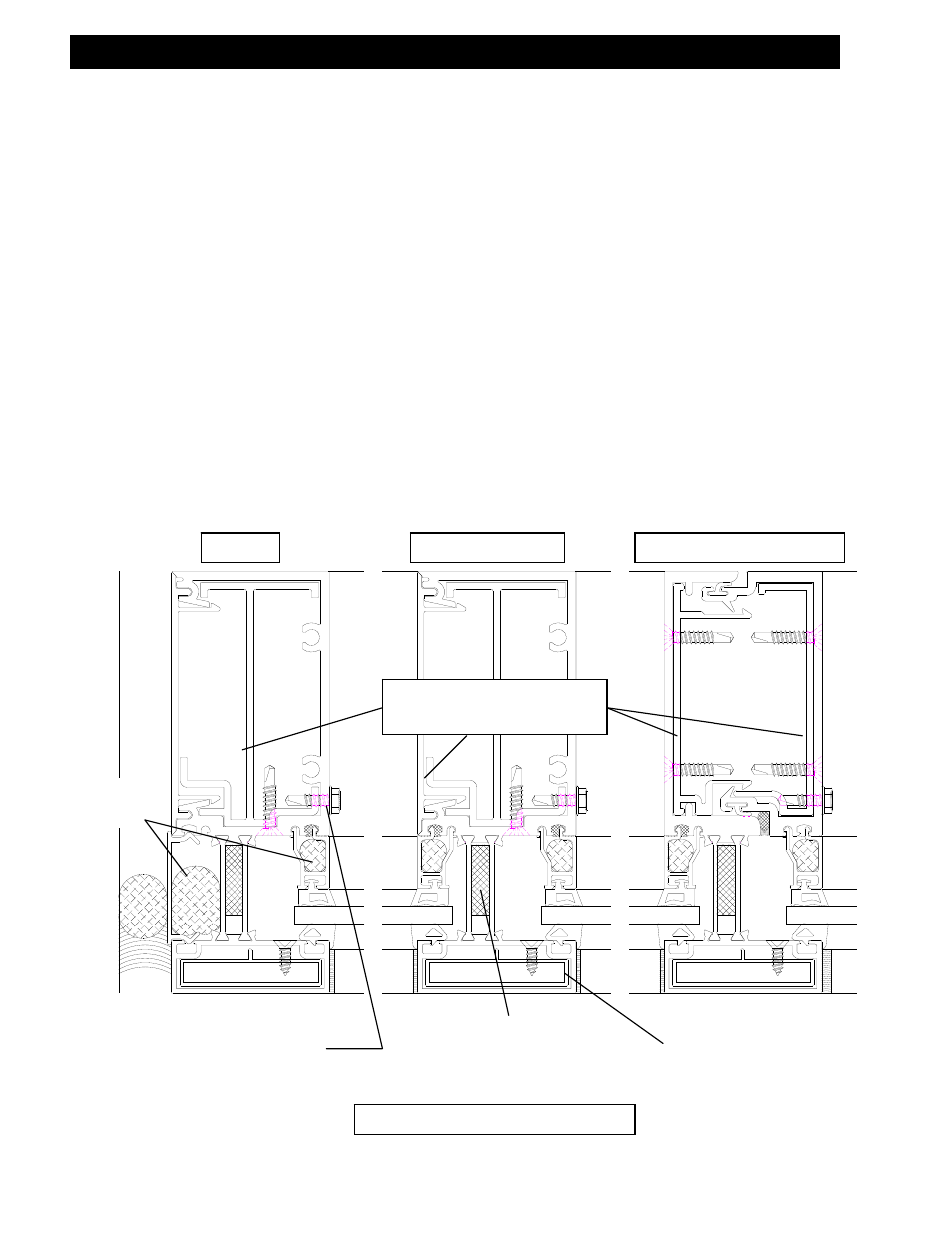
SPLICE SLEEVE
STOP SCREWS
BACKER
ROD
PLAN VIEW – MULLION SPLICE
Mullion splice sleeves
with bond breaker tape.
JAMB
INTERMEDIATE
EXPANSION MULLION
Cover splice sleeves
with bond breaker
tape.
¼” X 1” X 5” FOAM
CAULK JOINT BACKER