Spandrel at floor line – EFCO S5500 Advanced User Manual
Page 38
EFCO CORPORATION 6/2012 PART NO. Y557
38
Series 5500 Advanced & Alternate Installation Instructions
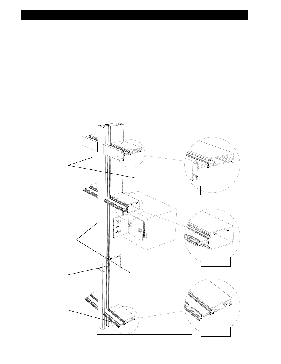
FIGURE A
FIGURE B
FIGURE C
VISION AREAS
SPANDREL AREAS
VISION AREAS
SPANDREL AT FLOOR LINE
SPLICE JOINT
FLOOR SLAB
Note: S-5500 curtain wall must be outside glazed at the floor lines, some column locations, shear
walls and parapet areas, or any other area that would not allow the glazing infill to be inside set.
Refer to the approved shop drawings for locations and exact configuration of the spandrel areas. The
following is a guide for a typical floor line spandrel installation.
Section VII: Glazing at Spandrel Areas of I.G. Frames
GLAZING SPANDREL AREAS AT FLOOR LINES
A. Vision lites will consist of inside glazed horizontals at the head of the lite as shown in
“FIGURE A” below.
B. The top of the spandrel lite and any intermediate horizontals within the spandrel areas will
consist of an outside glazed horizontal with a roll-on pressure cover as shown in “FIGURE B”
below.
C. The bottom of the spandrel lite above the vision area will consist of an inside/outside-glazed
horizontal with a roll-on pressure cover and removable interior bead as shown in “FIGURE
C” below. This will allow the spandrel lite to be outside set and the vision lite to be inside
set.