Connecting to the breakout board, Connecting to the shop air – Dynojet Spring Applied Air Release (SAAR) Brake Assembly User Manual
Page 22
Spring Applied Air Release (SAAR) Brake Assembly Installation
S P R I N G A P P L I E D A I R R E L E A S E ( S A A R ) B R A K E A S S E M B L Y I N S T A L L A T I O N
Installing the SAAR Brake Assembly
18
C
ONNECTING
TO
THE
B
REAKOUT
B
OARD
1
Connect the two black wires from the solenoid to the two terminals on the
breakout board labelled BRAKE (one to each terminal).
2
If you have a 4 wheel drive dyno model 224-248 or 224-224, refer to additional
instructions for “Four Wheel Drive Dynos” on page 20.
Figure 19: Connect the Brake Solenoid Wires to the Breakout Board
C
ONNECTING
TO
THE
S
HOP
A
IR
1
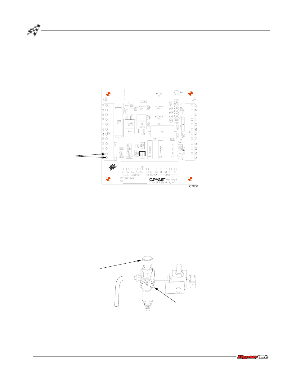
Connect shop air to the fitting on the brake air can pressure regulator. See
Figure 22 on page 21 if you are installing the brake on a four-wheel drive dyno.
2
Adjust the air pressure by pulling up on the regulator knob and turning
counterclockwise to decrease the pressure to 30 psi (clockwise to increase).
Note: The Spring Applied Brake should be operated at 100 psi, but you will start
with the pressure lower while connecting the air can to aid in lining up the parts.
Figure 20: Adjust the Air Pressure
connect the two black
wires from the brake
solenoid to the
breakout board
BR
A
K
E
0
AB092
pull up on regulator
knob and adjust
pressure to 30 psi
pressure gauge
should read 30 psi