Dynojet Spring Applied Air Release (SAAR) Brake Assembly User Manual
Page 10
Spring Applied Air Release (SAAR) Brake Assembly Installation
S P R I N G A P P L I E D A I R R E L E A S E ( S A A R ) B R A K E A S S E M B L Y I N S T A L L A T I O N
The Hydraulic Brake Assembly
6
5
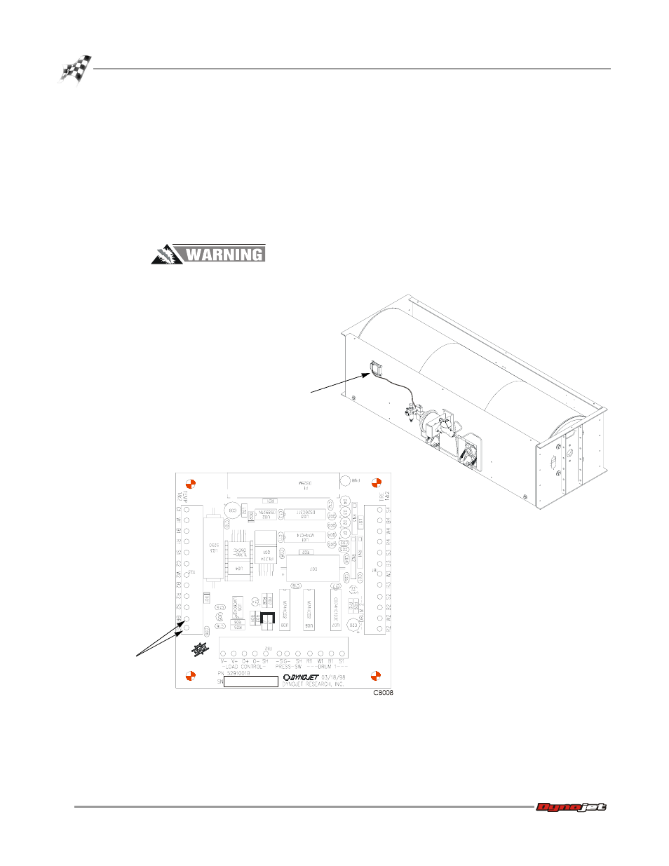
On standard dynos the brake control wiring is connected to the breakout board.
The breakout board is located on the dyno as shown in Figure 3.
Disconnect the two wires from the wiring block labeled BRAKE on the Breakout
board, as shown in Figure 3. These two wires connect the brake solenoid. It
should now be disconnected.
Note: If you are installing the upgrade on a four-wheel drive dyno, see “Four
Wheel Drive Dynos” on page 20 for the connections of the brake solenoid to the
movement board.
Never operate the dynamometer when the brake is not functioning.
Figure 3: Disconnect the Hydraulic Brake Control Wiring from the Breakout Board
AD167
disconnect
brake
assembly
wiring
BR
A
K
E
breakout
board