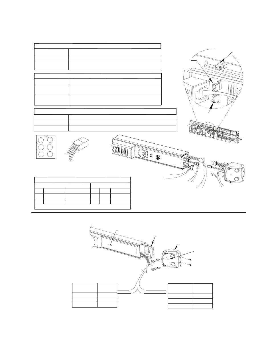
V40 ex, exxw, exv & exvxw wiring assemblies, Switch options, Figure 1 – Detex V40 EHxR User Manual
Page 10: Figure 3 p1 detail, Figure 2, Table 2 see see table 1, See table 5), See table 3 (jumper w/l9)
4
N.O. contact
Violet
Brown
Pin 1
Common
Pin 4
Contacts rated at 1.0A @ 30VDC or 0.5A @ 125VAC
Pin 5
Pin 6
Normally Closed
Yellow
Gray-Green
Pin 2
Pin 3
Normally Open
N.O. contact
Violet
----
----
Figure 3
P1 detail
1
2
5
3
6
P1 (see Fig. 3)
Figure 2
Battery Connector
(Standard)
(P1 wire usage)
Wiring Detail
Remote Signal
Table 5
(EHxR)
Bypass/Remote Signal
P2
J2
Remote Bypass
The device flashes one red LED and one beep about every 45 seconds
The Device gives no indication of battery being low.
On
Off (factory set)
J1
Protect wires
Switch selections must be made before applying power or installing battery (See Figure 1)
Table 2
See
See Table 1
Alarm sounds until turned off with key.
Unit sounds alarm as long as door is open.
Extended bypass is enabled.
Alarm turns off 2 minutes after door is closed
Auto Rearming Feature Setting
Status Description
Note: AC power must be applied
Table 3 (EH models only)
Disable Auto rearm
On (factory set)
Off
Disable Low Battery
Table 2
Status Description
The Device gives no indication of armed or disarmed status.
Status Indicator
On
Off (factory set)
SWITCH OPTIONS
Table 1
D
is
ab
le
A
U
TO
R
EA
R
M
Dis Lo Bat
ON
ON
O
N
IN
D
IC
AT
O
R
S
TA
TU
S
Fillerplate subassembly
Endcap bracket
Endcap
(see Table 5)
Figure 1
See Table 3
(jumper w/L9)
The Device flashes red or green LED every 3 seconds.
Red indicates armed status and green indicates disarmed.
12/24V AC/DC External Supply
(black wire)
Wire Color
Gray
Yellow
Brown
Connection
Closed
Open
Common
V40 EX, EXxW, EXV & EXVxW Wiring Assemblies
Connection
Wire Color
Common
Open
Closed
Yellow/Red
Gray/Red
Brown/Red
Install armored cable kit
(if required)
EX, EXxW (0.1A) for
signaling applications
EXV (3A), EXVxW (5A) for
power applications
101275 Page 10