Salter Brecknell 650 User Manual
Page 8
8
CHAPTER 2: GETTING STARTED
After unpacking the scale, a small amount of preparation is required before the scale can be
used. .
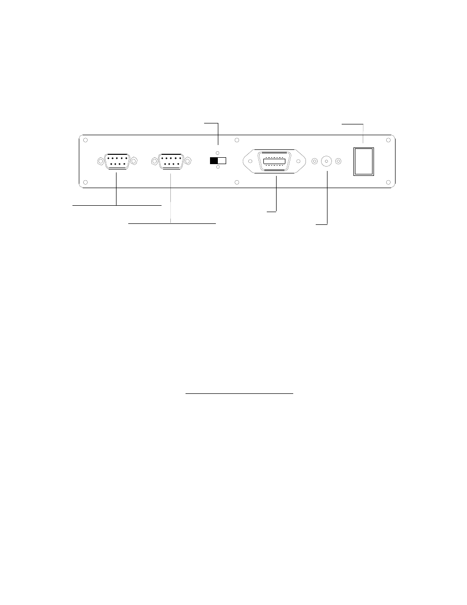
2.1 REAR PANEL
0
1
COM 1 Serial Port (RS-232)
Remote Scale Connector
DC Power Jack
ON/OFF Switch
COM 2 Serial Port (RS-232)
Battery Charger Switch
Figure 2-1: 650 Rear Panel
Step 1.
Position the scale in its area of intended use. Observe the following guidelines for
suitable location.
1. Choose a firm, stable floor or table.
2. Do not share an AC outlet with electrical noise producing equipment, such as
refrigeration units. This includes products with electrical motors and/or relays.
3. Do not place the scale in an area with changing ambient temperature and/or high
humidity.
4. Do not place the scale in an area prone to exposure to direct sunlight, wind, or dust.
5. Do not place the scale in an area with vibrating equipment.
Step 2
. Install the power supply - Non-battery-powered Units Only
1. After placing the scale in its area of use, locate the AC Adapter that shipped with the
scale.
2. Connect the female end of the AC Adapter to the connector on the rear of scale, and
then plug the adapter into an AC outlet.
Make sure that the AC voltage appearing
at the wall outlet matches the input voltage marked on the AC adapter.
Step 3
. If applicable, install the serial device(s).
1. Connect the optional serial printer using the serial cable supplied with the printer or
TTL Outputs to the COM1 port. See Appendix B for cabling requirements and pin
outs for TTL output.
NOTE:
If interfacing to a printer not supplied by Salter Brecknell, see Appendix B for
pin outs.
1. Connect the optional scanner or QWERTY keyboard or Bar Code Scanner to COM2
port. Both devices come with their own built-in cable.