Salter Brecknell 650 User Manual
Page 43
43
APPENDIX D: REMOTE SCALE WIRING
D.1 REMOTE SCALE WIRING
The 650 ships with a 15 ft shielded load cell cable for connection to the remote platform’s
load cell(s) or junction box. The 650 supplies enough current to drive up to 4-350
Ω
load
cells.
1.
Plug the cable’s 14-pin Centronics-type connector into the load cell port on the
rear panel of the scale.
2. Wire the bare wires and shield to the remote platform’s load cell(s) or junction box using
the color codes shown in Figure D-1.
Color
Wire Name
RED
+Excitation
BLK
–Excitation
GRN
+Signal
WHT
–Signal
Figure D-1: Color Codes for Shielded Load Cell Cable
3.
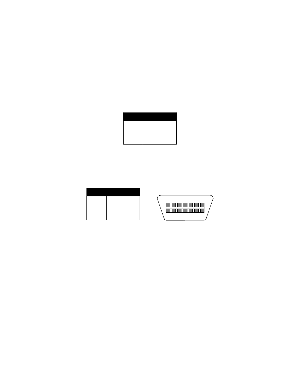
If you do not wish to use the shielded load cell cable, you may use own, following
the pin assignments shown in Figure D-2. (A 14-pin Male Centronics-type connector is
required).
Pin Nos.
Pin Name
1/8
+Excitation
3/10
–Excitation
5/12
+Signal
7/14
–Signal
7
1
5
3
14
12
10
8
Figure D-2: Pin assignments for the Load Cell Port
- PB500 (4 pages)
- PB250 (12 pages)
- MB2610 (4 pages)
- MBS Series (14 pages)
- 302BP (6 pages)
- 304BP (26 pages)
- 308BP (27 pages)
- APD-100 (36 pages)
- CB100 (8 pages)
- ESA Series (14 pages)
- LPS30 (18 pages)
- PC150 (13 pages)
- SP60 (9 pages)
- 3700LP (20 pages)
- C3235 (16 pages)
- C3255 (18 pages)
- C3225 (40 pages)
- B140 (32 pages)
- B120 (19 pages)
- B130 (22 pages)
- 610 (23 pages)
- 630 (24 pages)
- B220 (24 pages)
- B225 (44 pages)
- CS Series Crane (12 pages)
- 3800LP Series Calibrated with SBI-505 LED Indicator (22 pages)
- 405 (12 pages)
- LPS150 (30 pages)
- GP100 (13 pages)
- S100 (17 pages)
- PS150 (15 pages)
- S122 (63 pages)
- 6702 (28 pages)
- 6712 (24 pages)
- PS250 (28 pages)
- PS500 (19 pages)
- PS1000 (38 pages)
- PS3000HD (18 pages)
- SBI140 (35 pages)
- SBI100 (34 pages)
- SBI-521 (82 pages)
- 200 Series (47 pages)
- 200SL (2 pages)
- 400ES (30 pages)