B&M 81052 Stealth Magnum Grip Pro Stick Black Automatic Shifter. User Manual
Page 6
parts.
Step 29. Loosen the pinch bolt on the selector lever. This can
be either an Allen head bolt of a 12 point bolt head. Do not
remove the pinch bolt. Slightly pry the manual valve lever and
slide the selector shaft from the transmission. Discard the
selector shaft.
Step 30. This transmission includes the B&M Powerglide Pro-
lever shift level which is a two piece lever with separate lever
and shaft. Install the B&M selector shaft into the transmis-
sion with the lever pointing down. Hold the stock selector
lever in position in the case, engage the pin on the selector
lever with the manual valve and rotate the B&M shaft until the
flat on the shaft engages the serrations on the lever. Push
the B&M lever firmly into the transmission until the lever stops
on the shoulder of the shaft. Tighten the pinch bolt securely.
Step 31. Install the manual valve guide plate in place. (Make
sure that pin on the selector lever is engaged in the groove in
the manual valve.) Install the two bolts and tighten to 15 lbs.ft.
Install the detent roller spring. Hook the spring to the detent
roller and tab. The selector lever must travel freely and
smoothly from front to back with a positive click in each gear
position.
Step 32. Clean the oil pan and scrape the old gasket off of the
pan and case. (Note: If your pan does not have a drain plug,
you may wish to install a B&M Drain Plug Kit #80250, at this
time.) The old gasket can cause leaks. Install the oil pan with
the new gasket. Install the pan bolts except for the two center
bolts on the left side of the pan. Tighten the pan bolts to 8
lbs.ft. Do not overtighten as this can damage the pan gasket.
Step 33. Install the cable bracket in position with the two re-
maining pan bolts (See Figure #8). Install the B&M lever onto
the shaft with the lever pointing down. If your cable comes
from the front (usually a rear engined car), the lever is in-
stalled pointing upwards. You will have to make your own cable
bracket for this installation.
Step 34. Route the shifter cable according to Figure #3. Avoid
kinks and sharp bends and route the cable away from hot
engine or exhaust parts.
Remove the two rubber boots, one large nut, and a large
lockwasher from the threaded end of the shifter cable. Slide
the end of the cable into the cable bracket, install the large
nut and lockwasher loosely over the end of the cable. Install
the two rubber boots onto the end of the cable. Install the
swivel on the threaded end of the cable and position it in the
center of the threaded portion.
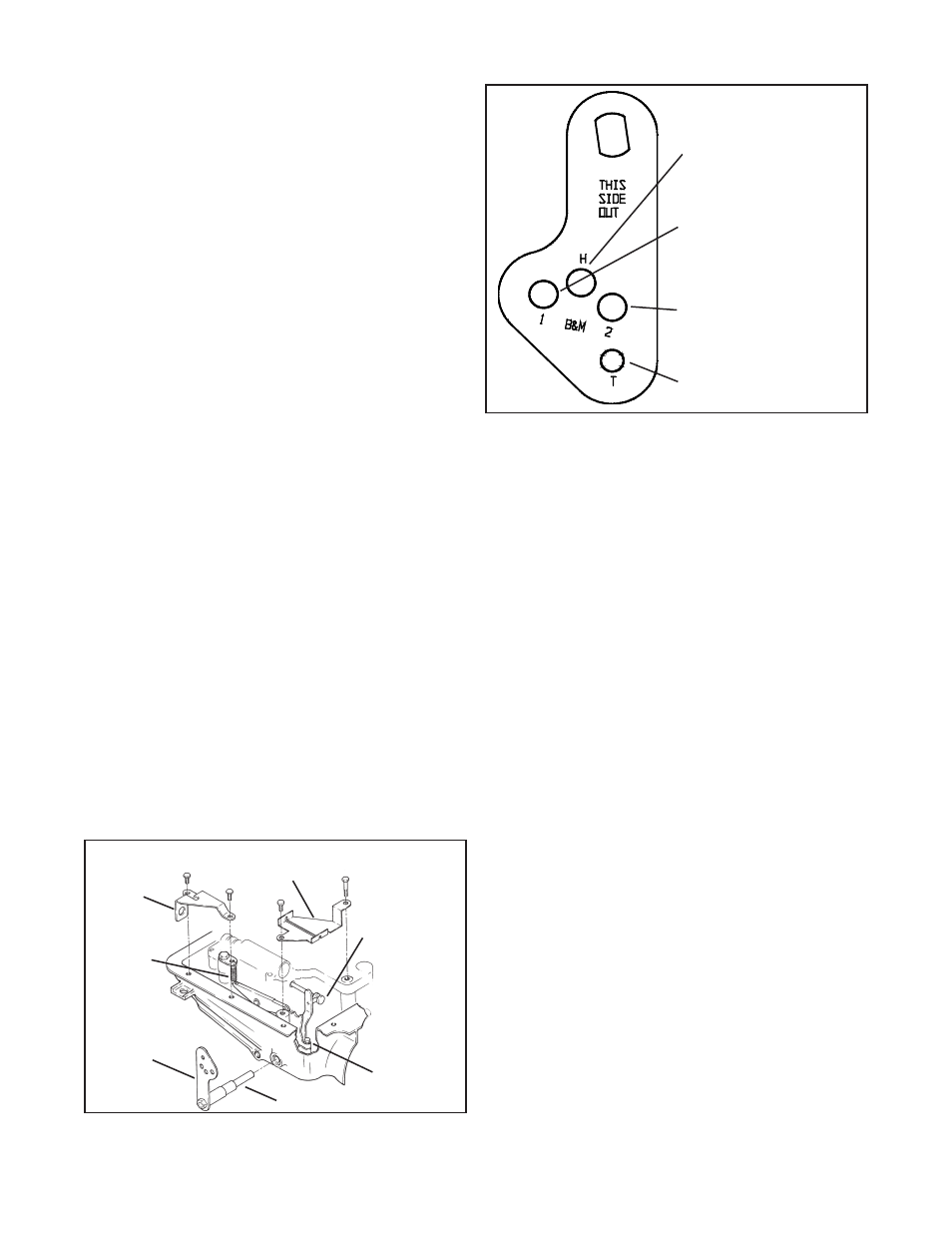
Step 35. Move the transmission selector lever by hand to full
rear position (Low). Operate the shifter lever to the Low gear
position (all the way back). Adjust the large nuts on the cable
so that the swivel will slide into the hole in the selector lever
that is labeled “H” (See Figure #9). Tighten the large nuts
completely. Be sure that the swivel will slide freely in and out
of the hole in the selector lever. Note: The shifter will not op-
erate correctly unless the hole marked “H” in the shift lever
is used.
Leave the swivel out of the hole and move the selector lever
to the Park position (all the way forward). Reinsert the swivel
into the hole marked “H” in the selector lever. Check to see
that the swivel will slide freely in and out of the hole marked
“H” in the selector lever in this position. If it does not slip in
freely, adjust the swivel slightly until it will slip into the hole
marked “H” in the lever.
Move the shifter back to the Low gear position and check that
the swivel will still slide easily in and out of the hole marked
“H” in the selector lever. (If you do not use the hole marked
“H” in the lever, it will be impossible to correctly adjust the
cable.) Operate the shifter through all the gear positions. Check
to make sure the swivel will slide in and out of the hole marked
“H” selector lever hole in each gear position. The shift cable
is now correctly adjusted. Install the cotter key supplied with
the shifter into the swivel and spread the key ends.
If you have a problem, DO NOT FORCE THE SHIFTER, this
will damage the cable, the shifter, or the transmission. Simply
start at the beginning and carefully check all your steps.
Step 36. Disconnect the battery ground cable to prevent acci-
dental shorts. Identify the neutral safety wires (engine will not
crank unless these wires are connected together). Extend the
wires to the shifter. Strip 1/4” insulation off the wires and in-
stall slip-on terminals supplied in kit. Crimp the terminals onto
the wires using a crimping tool or pliers. Connect the neutral
safety wires to the LOWER switch and the backup light wires
to the UPPER switch (See Figure #1). Tape the terminal con-
nections and all other connections to prevent shorts.
Reconnect the battery ground cable, disconnect the coil wire
and set the parking brake. Check the switch operation by at-
tempting to start the motor in each shifter position. The starter
must crank only when the shifter is in the Park or Neutral
position. Check the backup light operation when the shifter
Manual valve
guide plate
Cable bracket
mounts on
outside of oil
pan
Detent roller
spring
B&M shift
lever
B&M selector
shaft
Selector lever
pinch bolt
Manual valve.
Note that pin on
selector lever fits
in groove on
valve
Figure #8
Use this hole for Hurst
shifter and B&M Bandit
shifter, Magnum Grip Ban-
dit shifter, Pro Stick shifter,
and Magnum Grip Pro Stick
shifter
Use this hole for B&M
Megashifter or Street
Stick
Use this hole for B&M
Pro Ratchet, Quick Sil-
ver, Star Shifter, Z-
Gate or Quick Click
Use this hole for
Turbo Action Shifter
Figure #9
6