B&M 35229 TRANSPAK User Manual
Page 7
ing level as required. Test drive vehicle
and recheck for leaks while transmis-
sion is hot.
TROUBLE SHOOTING
Most problems can be traced to
incorrectly installed components. If the
transmission makes unusual noise or
feels as if it is binding up, turn off the
engine immediately. Go back and re-
check the entire installation.
If the problem is shift quality (slip-
ping, hard, early, late) then do the
following:
1. CHECK TRANSMISSION OIL
LEVEL.
2. CHECK AND ADJUST TV CABLE.
3. CHECK OUTSIDE MANUAL LINK-
AGE.
If the above does not remedy the
problem, then perform the following di-
agnostic oil pressure check:
1. CHECK ENGINE TUNE
2. INSTALL A 0-2,080 kPa (0-300
PSI) OIL PRESSURE GAGE. THE LINE
PRESSURE TAP IS LOCATED JUST
ABOVE THE OUTSIDE MANUAL LINK-
AGE ON THE LEFT HAND SIDE OF
THE CASE.
Check oil pressures in the following
manner:
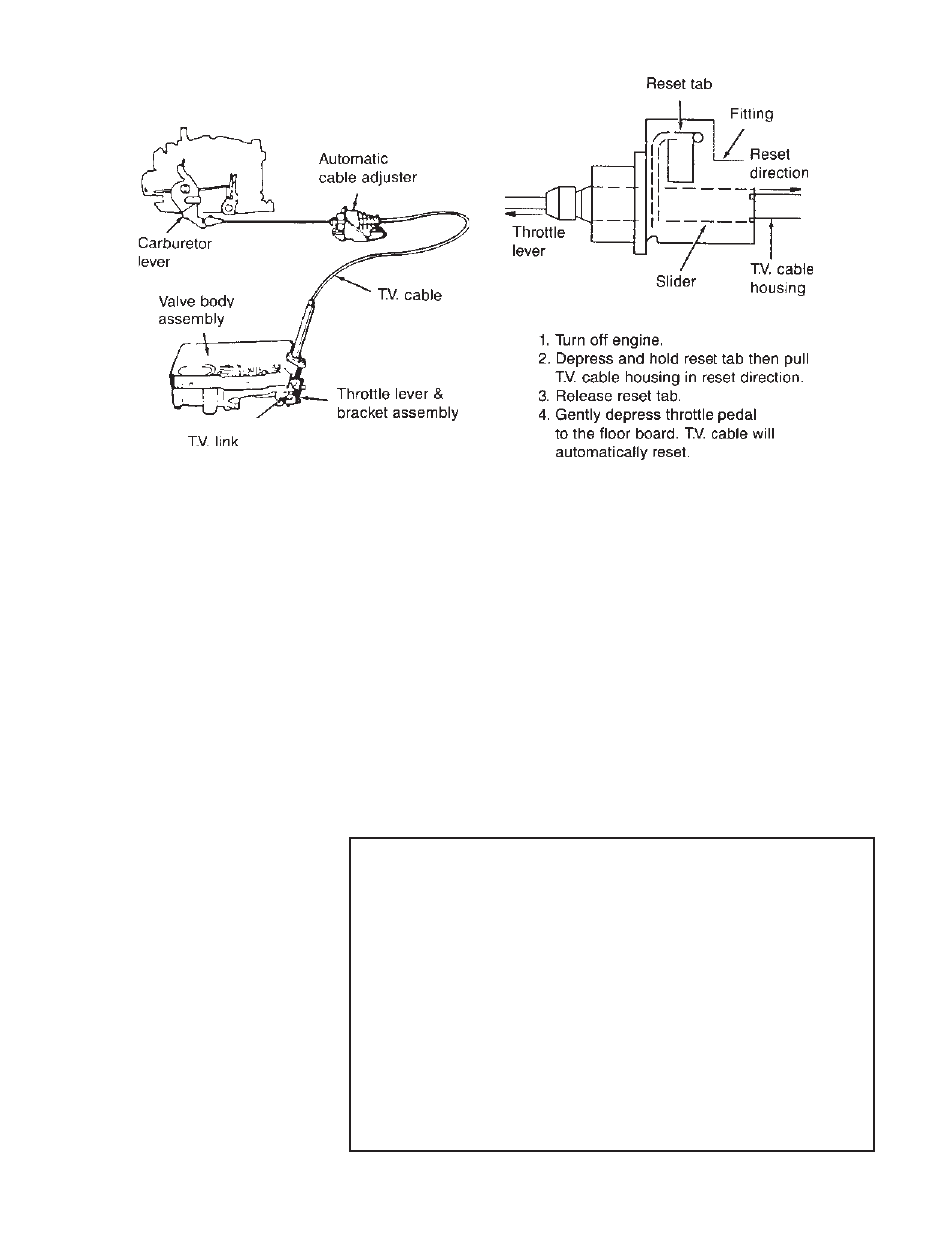
Minimum T.V. Line Pressure
Check: Set the T.V. cable (See Fig.
11) With the brakes applied, take the
line pressure readings at the selector
lever position and engine R.P.M. speci-
fied in the chart.
Maximum T.V. Line Pressure
Check: With the brakes applied, hold
or tie the T.V. cable in it’s fully extended
position then take the line pressure
readings again at the selector lever
positions and engine R.P.M specified
in the chart. IMPORTANT: Only ex-
tend the T.V. cable for this test. DO
NOT open throttle to wide open posi-
tion.
Basic line pressure is controlled by
the pumps output volume and the pres-
sure regulator valve. The T.V. system
which is controlled by the T.V. cable
causes line pressure to increase with
increased throttle opening. Because of
system requirements line pressure is
boosted by the reverse boost valve and
sleeve assembly when the selector is
in the Reverse, D2 or D1 position.
If the oil pressure readings are low,
high or do not change when the T.V.
cable is extended (except in D2 & D1
where pressure should remain con-
stant) then look at the pressure regula-
tor assembly for sticking valves or in-
correct order of assembly.
Fig. 11. T.V. Cable Adjustment Procedure.
7
T.V. Cable Resetting Procedure
TOOL LIST
Hydraulic jack
Gasket Scraper
Jack stands or Wheel ramps
3/8" Drill motor
Oil drain pan
Fine cut flat file
3/8" drive ratchet wrench
10mm, 13 mm, Sockets
Wet or Dry sand paper
Grease or petroleum jelly
Small punch or scribe
Torque wrench
Small flat screwdriver
Internal retaining ring pliers
Funnel
PARTS LIST
Pressure Regulator Valve
Pressure Regulator Spring (Blue)
Ring Retaining
Spring Line Bias (Red)
Gasket, Valve body upper
Gasket, Valve body lower
Gasket, Accumulator
Gasket, Oil pan
Oil Filter
Spacer, 3/8" (Red)
Spacer, 3/4" (Blue)
Drill, 3/32" (.094)
Drill, 5/64" (.078)