B&M 35229 TRANSPAK User Manual
Page 6
pressing the accumulator spring. To
avoid stripped threads make sure bolts
are fully engaged before attempting to
draw the accumulator up to the case.
STEP 16. Valve body installation.
Make sure check balls are in proper
locations. Position the manual valve so
the link rod can be engaged (See Fig.
1.) Do not force the manual valve at any
time. When the link and manual valve
are fully engaged, align the valve body
and case holes then install one bolt
finger tight to hold valve body in place.
Important: Make sure the manual valve
link is located as shown.
STEP 17. Install the throttle valve (TV)
linkage onto the valve body as shown,
make sure the T.V. exhaust checkball
lifter rod is correctly assembled. (See
Fig. 2.) IMPORTANT NOTE: The T.V.
cable MUST be reset before operat-
ing vehicle refer to step 22.
STEP 18. Carefully insert ends of the
signal oil pipe in their respective bores
and push them in evenly until fully
engaged. Engage all of the remaining
bolts to finish lining up the separator
plate and gaskets (See Fig.1.) Tighten
all the valve body and accumulator
bolts to 11 NM (8 Ft. Lb.) Avoid stripped
threads, Do not over tighten bolts.
Reconnect wiring harness connec-
tors to the terminals from which they
were removed. Refer to sketch or notes
made at Step 3. Reconnect the har-
ness to the case connector making
sure it is firmly seated and locked.
STEP 19. Double check installation: 1:
make sure all bolts are installed and
torqued. 2: Throttle valve linkage oper-
ates freely. 3: TV exhaust checkball
(#5) lift pin is properly installed. 4:
Wiring properly connected. 5: Regula-
tor valve retaining ring fully seated in
groove.
Place two O-rings on the end of the
new filter tube. Coat the O-rings with
clean ATF and push the tube into the
pump bore until it is fully seated. The
filter retainer clip should be located at
the small depression on the filter hous-
ing.
STEP 20. Remove all old pan gasket
material from pan and case pan rail.
Clean inside of pan with solvent. You
may want to install a B&M Drain plug kit
(80250) at this time. Install the new pan
gasket on the pan and align the holes.
Use grease or petroleum jelly to help
separator plate and gaskets to properly
line up before attempting to torque them.
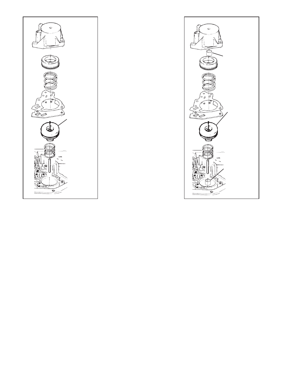
STEP 14. Heavy Duty Level Only;
Install gasket, piston, spring and 1-2
accumulator housing in reverse order of
removal. Tighten bolts finger tight (See
Fig. 9.)
STEP 15. Street Level Only; Remove
the spring and piston from the 1-2
accumulator housing (See Fig. 10.)
and install the Blue (3/4") spacer over
the guide pin. Install piston and spring
into 1-2 accumulator housing in reverse
order of removal. With the spacer in-
stalled it will be necessary to compress
the accumulator spring when installing
the accumulator assembly. To help
keep the separator plate and gaskets
aligned thread 5 or 6 bolts into the case
at various positions. Place gasket on
accumulator housing then hold the 1-2
accumulator assembly up to the case.
As an assembly aid use two of the long
valve body bolts as guides while com-
Fig. 9. Heavy Duty Level Accumula-
tor Assembly Order.
Fig. 10. Street Level Accumulator
Assembly Order.
hold the gasket in place during installa-
tion of pan. Do not use any gasket
sealer or silicone compounds. To
prevent premature band failure make
sure the servo exhaust hole shown in
(Fig. 1) is not obstructed. Place pan up
to case, align holes and install all bolts
finger tight. Tighten bolts to 14 NM (10
Ft. Lb.) Do not over tighten bolts. If the
bolts are over tightened the gasket will
deform excessively and result in oil
leaks.
STEP 21. Fill transmission with fresh
automatic transmission fluid to the full
mark on the dip stick. You will need
about 6 quarts.
STEP 22. You must reset the TV
cable, (See Fig. 11) for the correct
procedure. Failure to reset the TV
cable will result in poor shift quality
and, or transmission failure.
STEP 23. Inspect the transmission for
leaks with engine running. Lower ve-
hicle and check fluid level again adjust-
6
Note: Some
transmissions
come with the
3-4 accumula-
tor springs in-
stalled above
the piston. You
should reinstall
the spring as
shown here.
3-4 Accumulator
Piston
Note: Some
transmissions
come with the
3-4 accumula-
tor springs in-
stalled above
the piston. You
should reinstall
the spring as
shown here.
3-4 Accumulator
Piston
Red 3/8"
spacer
Blue 3/4" spacer