B&M 35229 TRANSPAK User Manual
Page 3
STEP 5. Remove the 1-2 accumula-
tor housing and plate while holding the
separator plate up to the case. Then
slowly lower the separator plate and
retrieve the (8) check balls located
above the plate. IMPORTANT: Make
note of the color, size and location of
the 1-2 and 3-4 accumulator springs for
correct reassembly. Remove all old
gasket material from these parts.
MODIFICATIONS
STEP 6. All Performance Levels;
Pressure regulator. Remove the snap
ring at the end of the pressure regulator
bore in the oil pump assembly (See
Fig. 3.) Use a screwdriver to hold the
pressure regulator assembly while re-
moving the retaining ring. If the sleeves
stick in the bore, lightly tap the sleeve
with a small rod and a mallet (piece of
2X4). Remove two sleeves with valves,
the pressure regulator spring and valve.
Reassemble the pressure regulator
assembly using the B&M pressure regu-
lator valve and the BLUE spring sup-
plied with the kit (See Fig. 4.) Use the
new retaining ring from the kit. Impor-
tant: Make sure the retaining ring is
firmly seated in its groove when as-
sembled.
CAUTION: The pressure regulator boost
valve train MUST be installed in the
proper order with the sleeves and valves
oriented as shown. There are several
ways the sleeves and valves can be
installed, however, only the orientation
shown will work properly. Improper in-
stallation will cause low line pressure,
resulting in slipping clutches and burnt
friction elements.
STEP 7. Heavy Duty and Street;
Separator Plate. Using the supplied
drills, enlarge the holes in your separa-
tor plate as indicated (see Fig. 5) for
the performance level desired. Pay close
attention to the diagram when locating
the holes to be enlarged so as not to
enlarge the wrong hole. Carefuly deburr
the holes after drilling.
STEP 8. Street Level Only; Line
bias valve. Rinse off valve body with
clean solvent to remove any dirt or grit.
Move to a clean working area. The valve
body consists of precision fit compo-
nents which will not tolerate dirt or
burrs. Remove the roll pin retaining the
line bias valve (See Fig. 6.) Remove the
aluminum plug, valve and spring from
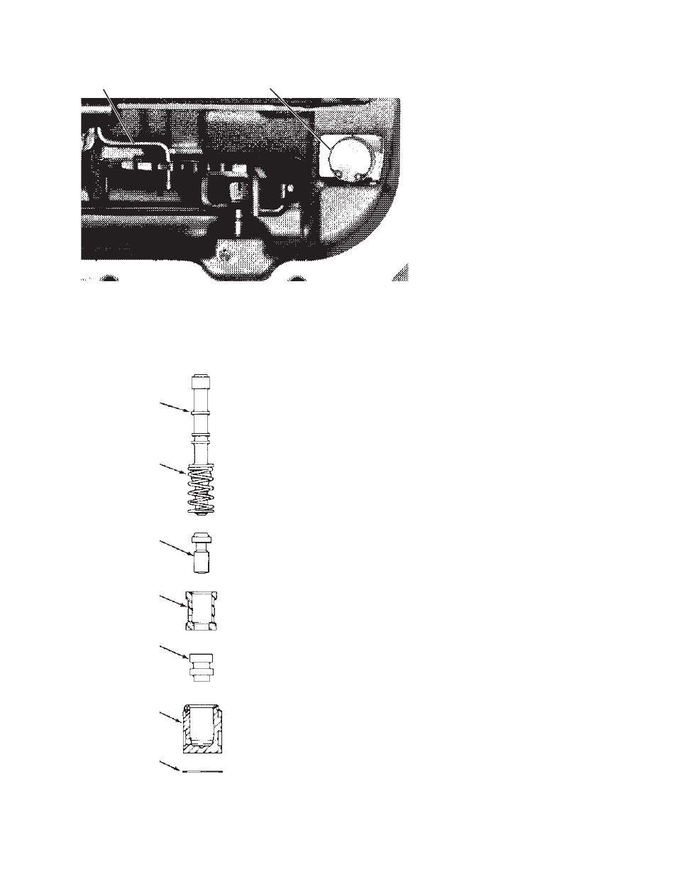
Make sure manual link is
installed as shown
B&M Pressure
regulator valve
Pressure regulator
spring
Reverse boost valve
Reverse boost valve
sleeve
T.V. boost valve
T.V. boost valve
sleeve
Pressure regulator
assembly retaining
ring
3
the pickup tube O-ring remains in the
pump bore, if so remove O-ring from
pump and discard both the O-ring and
filter.
STEP 3. (See Fig. 1) There are a
variety of different wiring harnesses
used on the TH-200-4R. Before pro-
ceeding further make a sketch and
some notes describing your particular
unit, recording which connectors go to
which switch. Disconnect the T.V. cable
connector from the throttle lever on
carburetor or throttle body. Remove
connectors from switches. Unplug the
wiring harness from case electrical
connector by prying the lock tab away
from the plug and pulling down on the
plug, do not pull on the wires. Re-
moving solenoid is not required, just tie
the wires up out of the way. Remove
signal oil pipe, detent spring, and the
throttle valve lever and bracket assem-
bly. Be careful not to lose the T.V.
exhaust checkball lifter rod when re-
moving throttle valve lever and bracket
assembly, (see Fig. 2.)
STEP 4. Remove all valve body bolts
except the center one (See Fig. 1.)
Hold the valve body up firmly with one
hand and remove the remaining bolt
slowly. Lower the valve body and disen-
gage the manual valve link. There are
several check balls in the valve body
along with several pints of oil. Have your
drain pan ready to catch the oil and
check balls (should they fall out.) Save
all (12) check balls in a safe place
where they won’t get lost.
I
Fig. 3. Pressure Regulator Bore.
Fig. 4. Pressure Regulator Assem-
bly.
Pressure regulator bore: Make sure
retaining ring is fully seated in groove