Get familiar with the aver hvc, Main system – AVer HVC130 user manual User Manual
Page 6
2
G
G
e
e
t
t
F
F
a
a
m
m
i
i
l
l
i
i
a
a
r
r
w
w
i
i
t
t
h
h
t
t
h
h
e
e
A
A
V
V
e
e
r
r
H
H
V
V
C
C
Main System
(1)
(2)
(3)
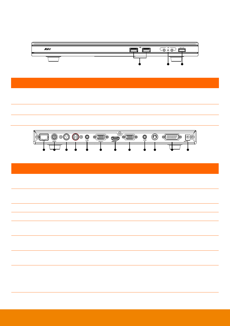
Main system front panel (fig. 1.1)
Name
Function
(1) USB Flash Drive port
Insert a USB flash drive. This allows you to save captured picture or
record the meeting in video format.
(2) Network Status
Check the network connection.
(3) Power
Turn on/off the main system.
(1)
(2)
(3) (4)
(5)
(6)
(7)
(8)
(9) (10)
(11)
(12)
VIDEO IN
DC 19V
AUX MIC IN
MIC IN
OUT
CAMERA IN
VGA IN
Main system back panel (fig. 1.2)
Name
Function
(1) LAN
Use an RJ-45 Ethernet cable and connect it to RJ-45 Ethernet port. Make sure
to connect AVer HVC to an IP-based network.
(2) RS-232
Connect it to a device with RS-232 interface. This allows you to integrate AVer
HVC with the central system device.
(3) AUX MIC IN Connect it to the central system device MIC.
(4) MIC IN
Receive the audio signal from the MIC.
(5) AUDIO OUT Output the audio signal from the main system on a TV thru RCA left and right
audio connection or amplified speaker.
(6) VGA OUT
Output the video signal from the main system on a flat panel monitor/LCD TV or
LCD/DLP projector thru RGB connection.
(7) HDMI OUT
Output the video signal from the main system on a HDMI monitor thru HDMI
connection. In Dual mode, this will be the main screen.
(8) VGA IN
Input the signal from a computer or other sources such as document camera.
Connect this port to the VGA output port of a device. Press PRESENT on the
remote and select VGA IN to share and display the video signal from this port
with the video conferencing camera image.
(9) AUDIO IN
Receive the audio signal from the audio device thru RCA left and right audio
connection.