Setting up the internal-mount model (ls-10), 1 setting up the ls-10 scanner, Rear panel – Nikon 35MM Film Scanner LS-10E User Manual
Page 28: Setting up the ls-10 scanner
Attention! The text in this document has been recognized automatically. To view the original document, you can use the "Original mode".
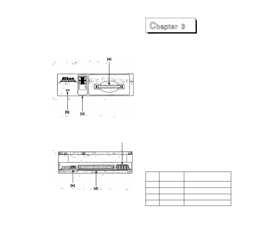
Fig. 3.1 The LS-10 scanner front view
Face avant du LS-10
Vorderansicht des Scanners LS-10
ra
Fig. 3.2 The LS-10 scanner rear view
Face arrière du LS-10
Rückseite des Scanners LS-10
Setting Up the Internal-mount
Model (LS-10)
The LS-10 scanner is easy to install. The following
instructions will lead you through this process.
3-1 Setting Up the LS-10 Scanner
Let’s take a look at the LS-10 internal-mount scanner as
shown in Figure 3.1. Note that the face of the LS-10 is
identical to the LS-10E scanner. The front of the scanner
includes the film slot, the focus control and the active
indicator.
[a] Insert slide here
[b] Active indicator
[c] Focus control
Rear panel
The rear panel of the LS-10 is shown in Figure 3.2. Note
that there are three items of interest on the rear panel.
These are the DC power connector, SCSI connector and
configuration DIP switch block.
[d] SCSI connector
[e] Configuration DIP switch
[f]
Power connector
The default DIP switch configuration is shown in Table
3.1. The meaning of the SCSI termination and the SCSI
ID DIP switch is discussed in this chapter. The LS-10
scanner is set at the factory to SCSI ID #5 and to
termination OFF. Note the connector on the right side of
the rear view of the LS-10 as shown in Figure 3.2. [t]
connector is unused when connecting the LS-10 inside
the computer.
DIP
Switch
Default
Usage
1
closed
SCSI ID bit 0 = 1
2
open
SCSI ID bit 1 = 0
3
closed
SCSI ID bit 2 = 1
4
open
SCSI ID Termination = OFF
Table 3.1 Factory set default DIP switch
configuration
28