Instailatlon step 10, Figure 4 – Craftsman 139.53225SRT User Manual
Page 22
Attention! The text in this document has been recognized automatically. To view the original document, you can use the "Original mode".
Instailatlon Step 10
instali the Safety Rewersing Sensor
Figures
2
and 3 show a;i.~ernbiy of brackets
and
“(7 wrap based on tfie fccommendcd instaflaiion of
tiio sensors as sftown on page 21.
However. Figures 4 and 5 arc; variations which may
fit your trsstailatiott requirements better. Make sure
the wraps and brackets are aligned so the
sensors will face each other across the garage
door.
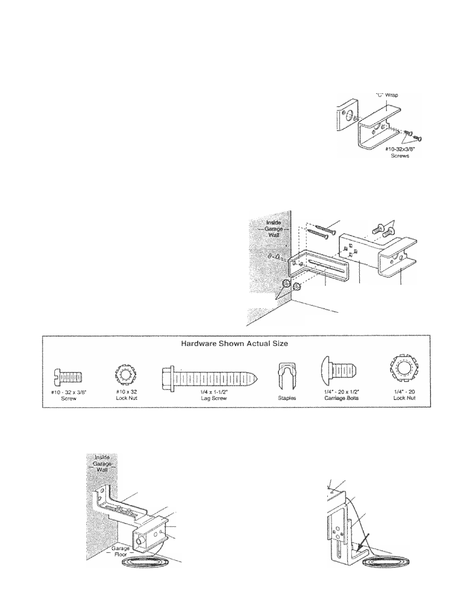
• Fristen the “C“ wraps to ttie mounting brackets
riavinfi square fiole;;. usinq the hardware sfiown
¡II Figure 2.
• Connact each accernbly to a siortfal Lirackot, ur.snrj
ti'se hordvvaru ufiowri
hi
Figure 5.
Note the alignment of the brackets for left and
right sides of fhe door.
• Finger tighten ihr, lock nuis,
• Use bracket niounting holes as a templale to
locate and dnii
(2)
3/16’ diamclor pilot holes on
both Sides of the garage door, 4"-6* above the
floor
biit no! exceeding 6‘.
(See warning on
pa.ge 21.|
• Attach bracket asse-m.bltes with iM'xl-l/S“ lag
screws as shown in Figure 3.
• Adjust -right and left side bracket assemblies to the
same distance out from the mounting syrface.
Make sure
all
door hardware obstructions are
cleared. Tight-e-n the
nuts
securely.
Figure 2
>i ur (¡ ^ f,K l-f *
/R K ,H HoF'h
^ J 'U
Figure 3
tM *
1
-
1
/
2
*
M*m %
IS* CsiTiBg« Bote
lag Soripwii {wBfc .s ■iÄWÄ; ««»Ä5 ifack'tt WÍ® Slot ^ Moorting 8r»cK0l wfth S<|u»» Hotos •C* Wr#P: Figure 4 Figure 5 Alternate Wat! Mount Mijonting S-faeket with Si« youiitfftg 8 racfc«! Witt! Separi Hole* C'Wrap Ssnsor with WÍT# ¡■«lical&f t,%ht ■mate Fl-oor Mount ■■. BSof wSti wtr* todicaiof tight MoMoting with Síjiia-rt Hci)«ä Bracket ' . with S1« Attach with eonere-l» ancho« (not piwid«d} FIOöl "■ 22