Erase logs, Display brightness – Taylor-Wharton CS Series User Manual
Page 37
35
CS SERIES
Erase Logs
ERASE LOGS is accessible through the menu system of the control. This menu choice
erases any of the four logs found in the control. Please note that once a log has
been erased, it is gone forever.
ERASE SYSTEM LOGS).
ERASE ERROR LOGS.
ERASE TEMPERATURE LOG #1.
ERASE TEMPERATURE LOG #2.
Display Brightness
DISPLAY BRIGHTNESS can be set through the menu system of the control. This
option changes the intensity of the display. The possible choices are 25%, 50%, 75%
and 100%.
Making Adjustments to the CS SERIES Control System Sensor
Assembly
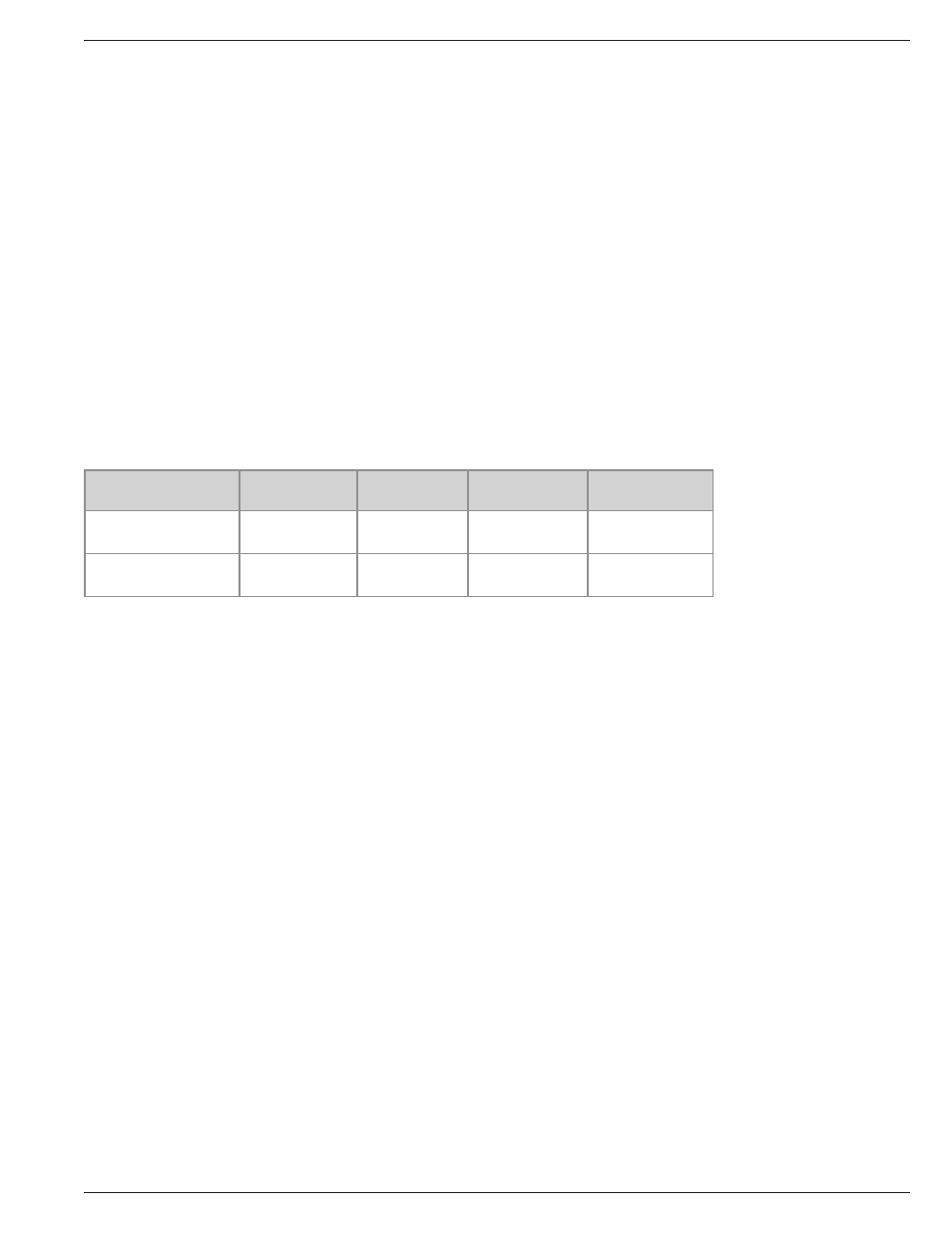
Table 5.0: CS SERIES Control System Sensor Assembly Factory Settings
CRYOSTORAGE
SYSTEM
LOW LEVEL
ALARM
START
FILL
STOP
FILL
HIGH LEVEL
ALARM
LABS
20K, 38K, 40K, 80K
2 in. (50mm)
3 in. (76mm)
5 in. (127mm)
(at carousel)
6 in. (152mm)
LABS 94K
5 in. (127mm) 6 in. (152mm) 9 in. (228mm)
(at carousel)
10 in. (254mm)
The sensor assembly is preset at the factory for vapor phase storage. If adjustments
need to be made, the following procedure will simplify the process.
The CS SERIES Control System control installed on the Taylor-Wharton Cryostorage
units operates with specially designed software to match the design characteristics of
your refrigerator. Refer to the chart below to see the versions and their difference.
To make adjustments to a sensor assembly in a refrigerator filled with LN
2
, the
following procedure can be used:
• Measure the LN
2
liquid level in the refrigerator.
• Take this measured level and subtract the offset to determine how many sensors
should be in liquid.
a. Remove sensors.
b. Fill to correct level and turn off Liquid supply.
c. Eg. Level is to be 15 in. (381 mm) and sensor number 6 is currently and will
remain the Stop Fill. 15 in. (381 mm) – 6 in. (152.4 mm) = 9 in. (238.6
mm) offset. Set Offset to 9 in (228mm).
• Go to “Test Level Sensor” through the CS SERIES Control System menu. “L”
means a sensor is in liquid while “G” means a sensor is in gas.
• Move the sensor up or down so that the appropriate numbers of sensors are in
liquid (read “L”).
• Return to the CS SERIES Control System main screen and the level indicated
should match the physically measured reading.
The Sensor Offset, the START FILL and the STOP FILL can all be set through the CS
SERIES Control System menu system.