Operating parameters – Taylor-Wharton CS Series User Manual
Page 16
14
CS SERIES
Power Supply
A 12 VDC power supply is supplied for the CS SERIES Control System. The system is
supplied with a transformer compatible with common household (North American)
100/240 VAC. (For other power outlets contact Taylor-Wharton Customer Service.)
UL approval for the system as a whole is not required since the control operates on
low voltage. If your power source differs, or is subject to disruption or line surges
due to other equipment on line, consult your Taylor-Wharton representative.
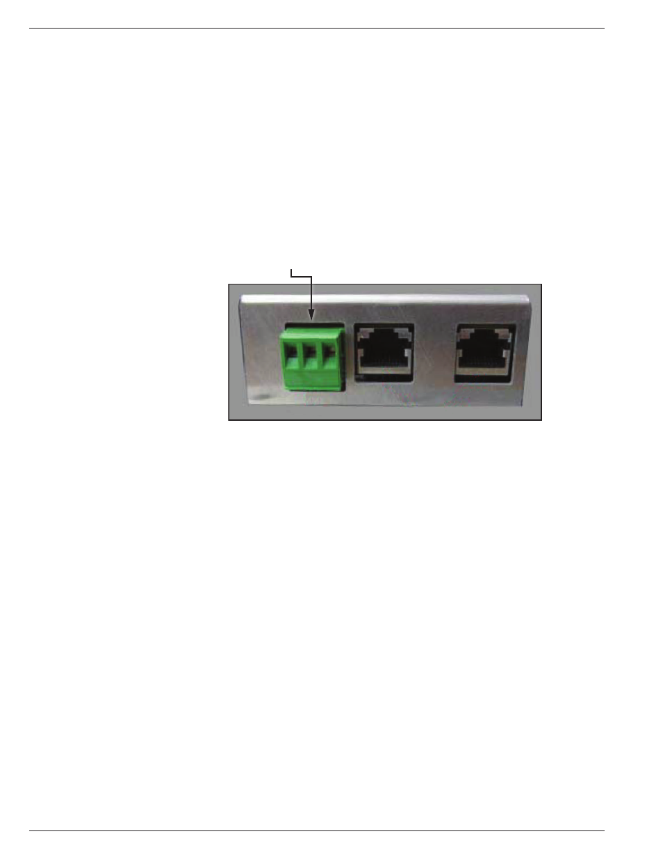
Remote Alarm
If an error condition occurs after a user defined period of time, a remote alarm
can be initiated. This is accomplished by connecting a remote device to the remote
alarm jack on the rear electrical panel. The 3-pin jack on the back of the unit
provides continuity between pin #2 (common) and pin #3 in the normal condition.
Continuity between pin #1 and pin #2 is provided in an error condition.
Remote Alarm Connector
Figure 5.0 Remote Alarm Plug Connection
Operating Parameters
When materials are immersed in liquid nitrogen, they will assume the temperature
of the liquid (-196°C/-320°F). When material is stored in the vapor phase over the
liquid, the liquid nitrogen is still a very cold refrigerant, but the refrigerator’s interior
temperature increases as product is stored higher over the liquid. This temperature
differential is not significant for many biological storage applications, and is affected
by the amount of product stored in the refrigerator, the type size and material of
inventory control system, and the liquid level in the unit.
The liquid level in the refrigerator is determined by the position of the of the
Thermistor Assembly in the sensor tube. These sensors are set at installation to
maintain a specific liquid level. A filling cycle is initiated when the level falls below
the Start Fill sensor and is completed when the Stop Fill sensor is reached. This
filling cycle repeats when the level fall below the Start Fill sensor. Sensor Probe
assignments may be changed on the controller keypad to define new start and stop
levels, and these levels may be set independently to vary the liquid level deference
between fills. Prior to the initial fill of the refrigerator, a determination should be
made whether vapor phase or liquid phase storage will be utilized.
All units are supplied with an eight thermistor assembly and a freeze-guard sensor
unless otherwise specified. The LABS factory setting positions will maintain liquid
level within a distance of 2 in. (50.8 mm) from the bottom of the operating tray on
the LABS 20K, 38K, 40K, 80K units, and 3 in. (76.2 mm) from the bottom of the
operating tray on the LABS 94K.