Caution warning, Important, Table 1 – Qmark EFQ Series - Commercial Fan-Forced Wall Heaters User Manual
Page 2
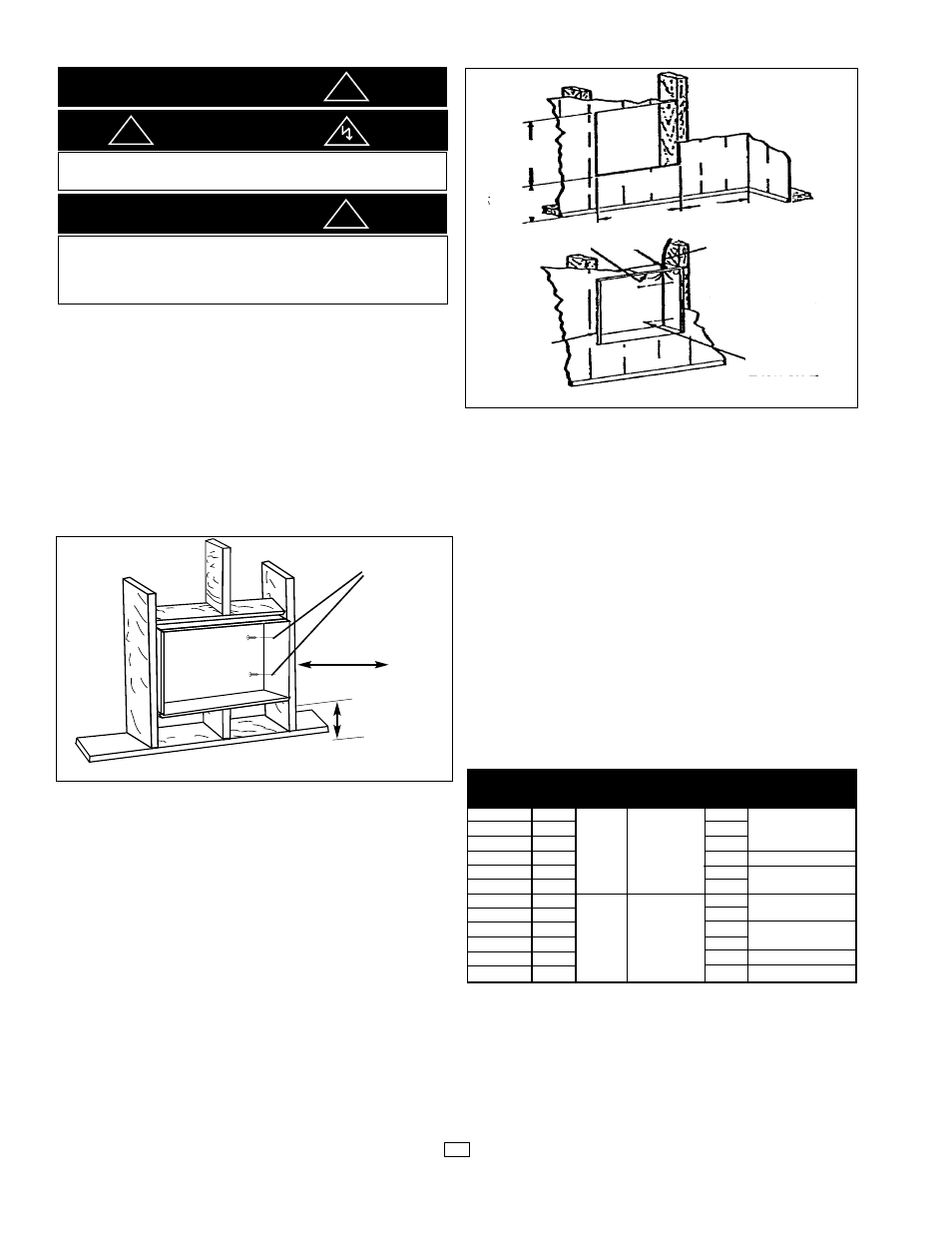
Installation of Recessed Back Box
in New Construction
1. Mounting Back Box (See Figure 1).
NOTE: Heater fan panels are installed into back box at
factory. These must be removed during the installation of
back box.
a. Place the back box between two 32" (812 mm)
center-to-center wall studs at the desired mounting
height but no closer than 8" (203 mm) to adjacent wall
or floor.
b. Align back box such that the bottom and sides will be
flush with finished wall surface.
c. Secure the back box in position with wood screws or
nails as shown in Figure 1.
2. Power Supply Wiring (See Figure 2)
NOTE: Wire compartment volume - 260in
3
(4260cm
3
).
a. Run a power supply cable into the knockout area in the
upper right hand corner of the back box. All wiring must
be in accordance with National and Local Electrical
Codes. Refer to Table 1 for correct wire size.
b. Remove disconnect switch bracket by removing two
screws on the left side of the disconnect switch cover.
c. Install a cable clamp in the “knockout” in the upper right
corner of the back box.
d. Insert power supply cable through cable clamp, allowing
at least 6" (152mm) of leads to extend inside the back
box. Connect the blue lead wires of disconnect switch to
the supply wire leads using wire connectors (see wiring
diagram, pg. 3.)
e. Ground the back box by connecting the supply ground lead
wire to the marked ground lug located in the upper right
corner of the back box.
f. Secure disconnect switch cover in place.
Installation of Recessed
Back box in Existing Construction
1. Provide a wall opening 30-1/2" (774mm) wide by 21-1/8"
(536mm) high at the desired mounting height, but no closer
than 8" (203mm) to floor or adjacent wall. (See Figure 2.)
2. Power Supply Wiring
NOTE: Wiring Compartment Volume - 260in
3
(4260cm
3
).
a. Run a power supply cable into the area above the top
of the wall opening. All wiring must be in accordance
with National and Local Electrical Codes. Refer to Table 1
for correct wire size.
b. Remove disconnect switch bracket by removing the
two screws on the left side of disconnect switch cover.
c. Install a cable clamp in the “knockout” in the top right
corner of back box.
d. Insert power supply cable through cable clamp, allowing
approximately 6" (152mm) of cable length to remain inside
the back box to facilitate connections.
3. Mounting Back Box
a. Place the back box into wall opening flush with finished
wall surface on bottom and sides of box.
b. Secure the back box in place with wood screws or nails.
(see Fig. 2)
4. Wiring Disconnect Switch
a. Connect the power supply wires to the blue wires of the dis-
connect switch using wire connectors (see wiring diagram, pg. 3)
b. Ground the back box connecting the supply ground lead
wire to the marked ground lug located in the upper right
corner of the back box.
c. Secure disconnect switch cover in place.
Installation of Back box with
Surface-Mounting Frame
(See Figure 3)
1. Secure back box to wall with knockouts in upper right hand
corner using screws and anchors.
NOTE: If heater is located in a high traffic area, where it may
be subjected to vandalism or abuse, take extreme care to see
that the box is firmly attached to the wall.
2. Power Supply Wiring
Notes:
• Wiring compartment volume: 260in
3
(4226cm
3
).
CAUTION
WARNING
DO NOT INSTALL HEATER UPSIDE DOWN OR SIDEWAYS.
DO NOT USE HEATER WITHOUT GRILLE.
FOR WALL MOUNTING ONLY. DO NOT INSTALL HEATER
CLOSER THAN 8" (203 mm) TO THE FLOOR OR ANY ADJA-
CENT WALL SURFACE. DO NOT INSTALL CLOSER THAN 36"
(915 mm) TO THE CEILING.
IMPORTANT
2
Fig. 1: Locating Recessed Back Box in New Construction
Fig. 2: Locating Recessed Back Box in Existing Construction
!
!
!
Table 1
Minimum Supply
Q6008
208
28.8
Q6004
240
25.0
10 AWG
Q6007
277
21.7
Q6003
347
1
6,000
17.3
12 AWG
Q60048
480
12.5
Q6006
600
10.0
14 AWG
Q8008
208
38.5
Q8004
240
33.3
8 AWG
Q8007
277
1
8,000
28.9
Q8003
347
23.1
10 AWG
Q80048
480
16.7
12 AWG
Q8006
600
13.3
12 AWG
8” minimum from
adjacent wall
nail or screw
(2 each side)
8” minimum from
floor
Back Box
Power supply cable
8” min (203mm)
30-1/2” (774mm)
Nail or screw
(2 each side)
Cable Clamp
Ground
Screw
Back
Box
21-1/8”
(536mm)
8”
(203mm)
Catalog #
Volts
Phase
Watts
Amps Wire Size