Room layout, Mounting height, Installation of single unit – Qmark DSH - Decorative Sill-Height Convectors User Manual
Page 4
Thermostat
24 amps @ 120-240 VAC
22 amps @ 277 VAC
Pilot duty– 125 VAC (all voltages)
Transformer relay
05A units:
22 amps @ 120-240 VAC
19 amps @ 277 VAC
07A-14A Units:
25 AMPS @ 120-240 VAC
22 AMPS @ 277 VAC
Power relay
25 amps @ 120-277 VAC- see wiring dia-
gram on heater
Disconnect switch
20 amps @ 120-277 VAC
4. Standard 75ºC wiring must be used in junction boxes, wire-
ways, blank sections, filler sections, and corner sections.
Room Layout
Refer to heating plans for exact room arrangements of heaters
(with or without thermostat and/or relays and/or switches and
accessories.)
Check the heater section dimensions and the additional wall
length required for telescoping accessories (Figure 1) before
starting wall-to-wall type installation. Be certain all heaters and
accessories needed are at hand and are of correct finish.
Mounting Height
At correct height, draw a pencil line on the wall, level and/or par-
allel with the window sill. Minimum mounting heights above the
floor shall be as follows:
Minimum Mounting Height Above Floor
Watts/Ft. Heater Length
Bottom Inlet/Front Inlet
125, 188 and 250 Watts/Ft.
1-3/4”
0”
376, 500, 625, and 750
3”
0”
Watts/Ft.
Note: Up to 3/4” thick floor covering, such as carpet, tiles,
linoleum, etc., may be installed around and under the heater
without adversely affecting the performance of the heaters.
Installation of Single Unit
Note: For ease of installation, it is important that the sequence
of operations indicated below be followed in order.
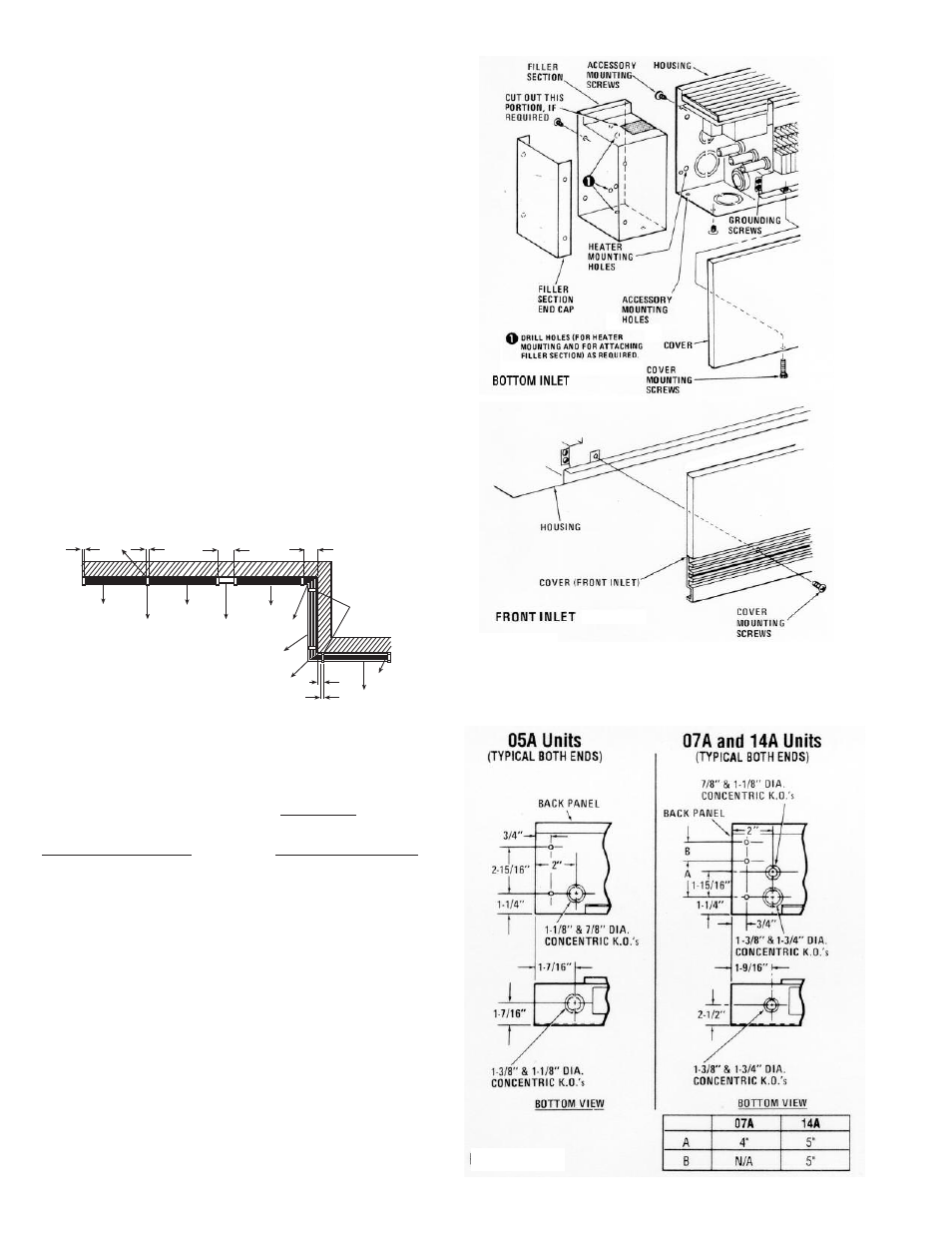
1. Remove front cover by removing mounting screws (Figure
2).
2. Remove appropriate electrical knockout from either junction
box. See Figure 3 for location of knockouts.
3. Install end caps (must be purchased separately) on both
ends of the heater housing. Refer to Figure 4 for details of
end cap installation.
Figure 3
4
HEATER
HEATERS
BUTTED
TOGETHER
HEATER
FILLER
SECTION
HEATER
INSIDE
CORNER
HEATER
OUTSIDE
CORNER
HEATER
END
CAP
TYPICAL INSTALLATION
SPLICE PLATE
KIT
SPLICE PLATE
KIT
Figure 1
Typical Installation
See page 9 for N dimensions
N
N
N
N
N
N
10
10
7
3
1
2
4
8
5
9
6
Figure 2