Warning – Qmark CDF - Commercial Downflow Ceiling Mounted Heaters User Manual
Page 4
16. Run the power supply cable through the connector, leav-
ing about 8” (203mm) of wire inside the recess mounting
box. (Power supply cable must be #10 AWG min. rated
90°Cmin.)
17. Connect the ground wire to the green ground screw on
the recess mounting box.
18. After wiring is complete, replace and secure the side of
the recess mounting box previously removed in Step 2.
19. Install discharge air grilles. (Refer to “Installation of
Discharge Air Grilles”, page 5.)
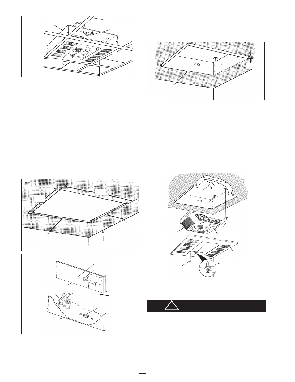
INSTALLATION OF RECESS MOUNTED
HEATER IN PLASTER CEILING
1. Determine the desired location of the heater. SEE
WARNING NO. 4 FOR MIN. MOUNTING
CLEARANCES AND WARNING NO. 9.
2. Cut a 22-1/4” x 22-1/4” (565mm x 565mm) mounting
hole in the ceiling for the recess mounting box (Figure
5).
3. Remove the Recess Mounting Box (Figure 6) from the
carton containing the Recess Mounting Enclosure, Type
REA.
4. Remove one of the knockouts and install a cable or con-
duit connector (Figure 6).
5. Install the optional disconnect switch (if required) as
shown in Figure 6.
6. Run the power supply cable through the connector, leav-
ing about 8” (203mm) of wire inside the recess mounting
box. (Power supply cable must be #10 AWG min. rated
90°C min.)
7. Place the recess mounting box in the ceiling opening
and align the marks on the sides of the mounting box
with the bottom of the finished ceiling (Figure 7). This
will position the edge of the mounting box 3/8” (9,5mm)
below the ceiling and will allow the recess face plate to
lay flat against the ceiling.
8. Secure the recess mounting box to the building structure
using a minimum of four fasteners (not supplied).
9. Remove the heater section from its carton.
10. Install optional controls (if required) into the heater sec-
tion in accordance with the Instruction Sheet packaged
with the control.
11. To wire the heater, and/or to convert from single to
three-phase voltage, refer to “Electrical Wiring” (Figure
12, page 5).
12. Position the heater section over the studs in the recess
mounting box (Figure 8).
NOTE: The end of the heater section with the terminal
block must be positioned at the end of the recess mounting
box where the supply wiring enters.
13. Push the heater section onto the studs and securely
tighten four nuts (supplied) on the studs to secure the
heater section to the recess mounting box (Figure 8).
14. Connect the ground wire to the green ground screw on
the recess mounting box.
15. Remove the recess face plate (Figure 8) from the carton
containing the Recess Mounting Enclosure, Type REA.
16. Position the recess face plate over the heater
section/recess mounting box, making sure that the
thumb pins are in the holes in the heater section.
NOTE: The thumb pins are an aid to help position and hold
the recess face plate during installation. Additional sup-
port (Step 18) is required.
4
Figure 4
Figure 5
Figure 6
Figure 7
Figure 8
Power Supply
Cable
T-
Bar
Grid
Heater
Wall
Wall
12”(305mm) Min.4kw
24”(609mm) Min. 5kw
12”(305mm) Min.4kw
24”(609mm) Min. 5kw
Wall
Wall
Wall
Wall
22-1/4”
(565mm)
22-1/4”
(565mm)
12”(305mm) Min.4kw
24”(609mm) Min. 5kw
8”(2438mm) to Floor Min.
14”(4267mm) to Floor Max..
12”(305mm) Min.4kw
24”(609mm) Min. 5kw
Optional
Disconnect
Switch
Recess
Mounting
Box
Recess Mounting
Box
Recess Face
Plate
Heater
Section
Insure that “Thumb Pin” is pulled
out before positioning the face
plate on the heater section.
Depress “Thumb Pin” after face
plate is sealed firmly against the
heater section.
Thumb Pin Hole
Nut (4)
Stud (4)
Screw (4)
Power
Supply
Cable
3/8” (9.5mm)
Recess
Mounting Box
Cable or
Conduit
Connector
1/2” (12.2mm)
Knockout
Screw (2)
1/2” (12.2mm)
Knockout
7/8” & 1-1/8”
(22.2 & 28.5mm)
Nested Knockout
7/8” & 1-1/8”
(22.2 & 28.5mm)
Nested Knockout
Grounding
Screw
WARNING
FAILURE TO INSTALL THE FOUR MOUNTING NUTS
COULD RESULT IN THE HEATER FALLING. (SEE FIG. 2)
!