Important, Warning, Unpacking instructions – Qmark CDF - Commercial Downflow Ceiling Mounted Heaters User Manual
Page 2: Installation of surface mounted heater
IMPORTANT NOTICE
- This heater is wired so the fan will come
on with no delay when energized as the thermostat is calling for
heat. When the thermostat is satisfied, the fan must continue to run
until the heater has cooled to a safe temperature. If an external
thermostat or controls are to be used, DO NOT wire heater so ther-
mostat shuts power to fan. The heater will be damaged and the
warranty will be voided. Thermostat must be connected as shown
on wiring diagram (Fig. 12) for correct operation.
NOTE: Field wiring must be #10 AWG. min. rated 90°C,min.
Wiring Compartment Volume: 252in
3
(4130cm
3
)
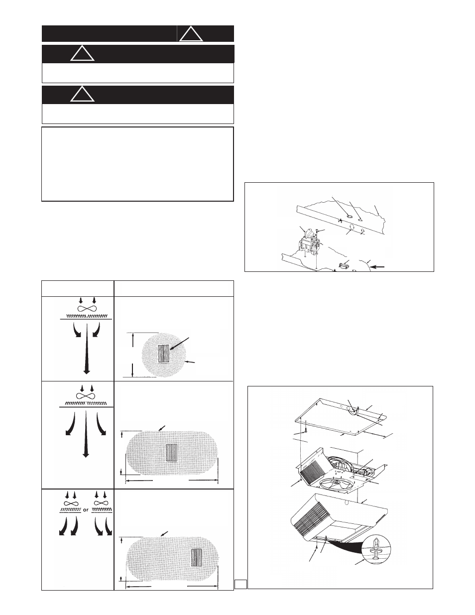
ADJUSTABLE DISCHARGE GRILLES
CUSTOM AIR FLOW PATTERNS
1. The discharge air pattern is determined by the arrange-
ment of the discharge grilles.
2. Care must be taken when selecting location of heater.
NOTE: The discharge grill area is rectangular; the discharge
grilles can only be installed parallel to the intake louvers.
UNPACKING INSTRUCTIONS
This heater is shipped in two cartons.
1. One carton contains the Heater Section, consisting of the
fan, heating elements and controls (Models 542, 547,
548, 557 & 558).
2. The other carton contains the Mounting Enclosure.
There are two types of enclosures: a) Recessed
Mounting Enclosure, Type REA and b) Surface Mounting
Enclosure, Type SEA. Either enclosure is acceptable
with any of the Model 500 Series heater sections.
Both a Heater Section and a Mounting Enclosure are
required to complete the installation of this heater.
INSTALLATION OF SURFACE MOUNTED HEATER
1. Determine the desired location of the heater. See warn-
ing No. 4 for min. mounting clearances.
2. Remove the Surface Mounting Plate (Figure 1) from the
carton containing the Surface Mounting Enclosure, Type
SEA.
3. Remove one of the knockouts and install a cable or con-
duit connector.
4. Install the optional disconnect switch (if required) as
shown in Figure 1.
5. Run the power supply cable through the connector, leav-
ing about 8” (203mm) of wire inside the surface mounting
plate. (Power supply cable must be # 10 AWG min. rated
90°C min.)
IMPORTANT
!
Field Conversion for Lower Wattage Rating
(Figure 12)
To convert the heater to a lower wattage rating, completely remove
one(1) red jumper wire from one heating element for 25% wattage
reduction. Completely remove two (2) red jumper wires for a 50%
wattage reduction. Discard the jumper(s). Be sure the remaining
wires are securely connected.
Conversion for 3Ø Installation
Heater is factory wired for connection to 1Ø only. To convert to 3Ø,
remove and discard blue jumper wire between L1 & L3. (See Fig. 12,
page 5).
Figure 1
Figure 2
WARNING
FAILURE TO INSTALL THE FOUR MOUNTING NUTS
COULD RESULT IN THE HEATER FALLING. (SEE FIG. 2)
!
WARNING
FAILURE TO INSTALL THE FOUR SCREWS, COULD ALLOW
THE SURFACE WRAPPER TO FALL. (SEE FIG. 2)
!
Discharge Air
Grille Arrangement
Custom Air
Flow Pattern
NARROW AIR PATTERN for high ceiling
applications (11’(3352mm) to 14’(4267mm)),
concentrates the heated air to ensure full pen-
etration to the floor level.
8’
(2438mm)
24’(7315mm)
17’(5181mm)
8
’(
2
4
3
8
m
m
)
1
0
’(
3
0
4
8
m
m
)
Heater
Discharge
Grilles
7/8”(22,2mm) &
1-1/8”(28.6mm)
Nested Knockout
1/2”(12.7mm)
Knockout
1/2”(12.7mm)
Knockout
Cable or conduit
connector
Optional
Disconnect Switch
Surface Mounting
Plate
7/8”(22,2mm)
Knockout
Surface
Mounting Plate
Screw (2)
Air Pattern
on Floor
Air Pattern on Floor
Air Pattern on Floor
Screws or
Bolts
(Not Supplied)
Grounding
Screw
Surface Mounting
Plate
Power Supply
Cable
Thumb Pin
Hole (2)
Thumb Pin
Hole (2)
Insure that “Thumb Pin” is pulled out
before positioning the surface wrapper on
the heater section. Depress “Thumb Pin”
after surface wrapper is sealed firmly
against the heater section.
Heater Section
Surface Wrapper
Screw (4)
12”(305mm) Min.4kw
24”(609mm) Min. 5kw
12”(305mm) Min.4kw
24”(609mm) Min. 5kw
Stud (4)
Nut (4)
WIDE AIR PATTERN for standard ceiling
applications (8’(2438mm) to 10’(3048mm)),
disperses the air to give a gentle, less pro-
nounced pattern while circulating all the air
from floor to ceiling.
ASYMMETRICAL AIR PATTERN directs
heated air in a specific direction, allowing
the heater to be located where space allows
with the heated air delivered to where it is
required.
2