Warning – Qmark CDF - Commercial Downflow Ceiling Mounted Heaters User Manual
Page 3
6. Position the surface mounting plate against the ceiling
and secure with bolts or screws (Figure 2). See
Warning No. 9. Connect the ground wire to the green
ground screw on the surface mounting plate.
7. Remove the heater section from its carton.
8. Install optional controls (if required) into the heater sec-
tion in accordance with the Instruction Sheet packaged
with the control.
9. To wire the heater, and/or to convert from single to
three-phase voltage, refer to “Electrical Wiring” (Figure
12, page 5).
10. Position the heater section over the studs on the surface
mounting plate (Figure 2).
NOTE: The end of the heater section with the terminal
block must be positioned at the end of the surface mounting
plate where the supply wiring enters.
11. Push the heater section onto the studs and securely
tighten four nuts (supplied) on the studs to secure the
heater section to the surface mounting plate (Figure 2).
12. Remove the Surface Wrapper from the carton containing
the Surface Mounting Enclosure, Type SEA.
NOTE: Insure that the “thumb pin” in each end of the dis-
charge grille opening is pulled outward to allow the body of
the thumb pins to fit into the holes in the heater section.
(Figure 2).
13. Position the surface wrapper over heater section/surface
mounting plate, making sure that the thumb pins are in
the holes in the heater section.
14. With the surface wrapper seated firmly against the
heater section, depress the “thumb pins”. This will
cause the thumb pins to expand and will temporarily
hold the surface wrapper in place.
NOTE: The thumb pins are an aid to help position and hold
the surface wrapper during installation. Additional support
(step 15) is required.
15. Install and securely tighten four screws (supplied) to secure
the surface wrapper to the heater section (Figure 2).
16. Install discharge air grilles. (Refer to “Installation of
Discharge Air Grilles”, page 5.)
INSTALLATION OF RECESS MOUNTED
HEATER IN T-BAR CEILING
The recess mounted heater will mount in any standard 2’ x
2’ (609mm x 609mm) T-Bar (drop) ceiling. SEE WARNING
NO. 4 FOR MIN. MOUNTING CLEARANCES & WARNING
NO. 9.
1. Remove the recess mounting box (Figure 3) from the
carton containing the Recess Mounting Enclosure, Type
REA.
2. Remove three screws and the side of the recess mount-
ing box to allow for easier wiring (Figure 3).
3. Remove one of the knockouts and install a cable or con-
duit connector (Figure 3).
4. Install the optional disconnect switch (if required as
shown in Figure 3).
5. Remove the heater section from its carton.
6. Install optional controls (if required) into the heater sec-
tion in accordance with the Instruction Sheet packaged
with the control.
7. To wire the heater, and/or to convert from single to
three-phase voltage, refer to “Electrical Wiring” (Figure
12, page 5).
8. Position the heater section over the studs in the recess
mounting box (Figure 3).
NOTE: The end of the heater section with the terminal
block must be positioned at the end of the recess
mounting box where the supply wiring enters.
9. Push the heater section on to the studs and securely
tighten four nuts (supplied) on the studs to secure the
heater section to the recess mounting box (Figure 3).
10. Remove the Recess Face Plate (Figure 3) from the car-
ton containing the Recess Mounting Enclosure, Type
REA.
NOTE: Insure that the “thumb pin” in each end of the dis-
charge grille opening is pulled outward to allow the body of
the thumb pins to fit into the holes in the heater section.
(Figure 3.)
11. Position the recess face plate over the heater
section/recess mounting box, making sure that the
thumb pins are in the holes in the heater section.
12. With the recess face plate seated firmly against the
heater section, depress the “thumb pins”. This will
cause the thumb pins to expand and will temporarily
hold the recess face plate in place.
NOTE: The thumb pins are an aid to help position and hold
the recess face plate during installation. Additional support
(Step 13) is required.
13. Install and securely tighten four screws (supplied) to
secure the recess face plate to the heater section
(Figure 3).
14. Determine the desired location of the heater.
15. Position the heater in the T-bar grid (Figure 4) and
secure as required. SEE WARNING NO. 9.
3
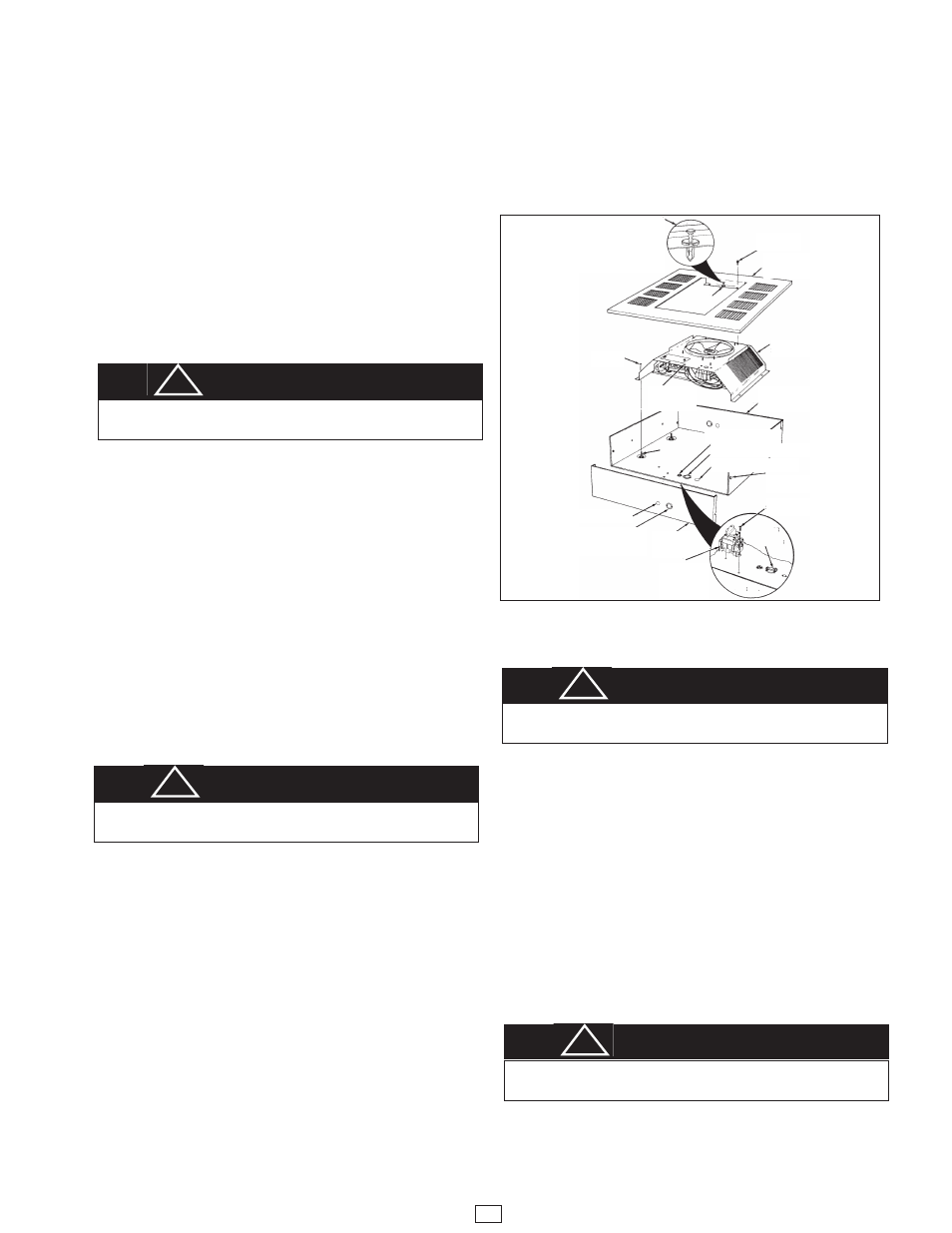
Figure 3
Thumb Pin
Hole (2)
Thumb
Pin (2)
Insure that “Thumb Pin” is pulled out
before positioning the face plate on
the heater section. Depress “Thumb
Pin” after face plate is sealed firmly
against the heater section.
Screw (4)
Screw (3)
Screw (2)
Recess Face
Plate
Recess
Mounting Box
Heater Section
Nut (4)
Stud(4)
Cable or
conduit
connector
Optional
Disconnect
Switch
1/2” (12.7mm) Knockout
7/8” & 1-1/8” (22.2mm & 28.5mm) Knockout
7/8” & 1-1/8”
(22.2mm & 28.5mm)
Nested Knockout
1/2”(12.7mm) Knockout
Side
Panel
Grounding Screw
WARNING
FAILURE TO INSTALL THE FOUR MOUNTING NUTS
COULD RESULT IN THE HEATER FALLING. (SEE FIG. 2)
!
WARNING
FAILURE TO INSTALL THE FOUR MOUNTING NUTS
COULD RESULT IN THE HEATER FALLING. (SEE FIG. 2)
!
WARNING
FAILURE TO INSTALL THE FOUR SCREWS, COULD ALLOW
THE SURFACE WRAPPER TO FALL. (SEE FIG. 2)
!
WARNING
FAILURE TO INSTALL THE FOUR SCREWS, COULD ALLOW
THE SURFACE WRAPPER TO FALL. (SEE FIG. 2)
!