Dell Studio XPS 435T / 9000 (Early 2009) User Manual
Page 29
9.
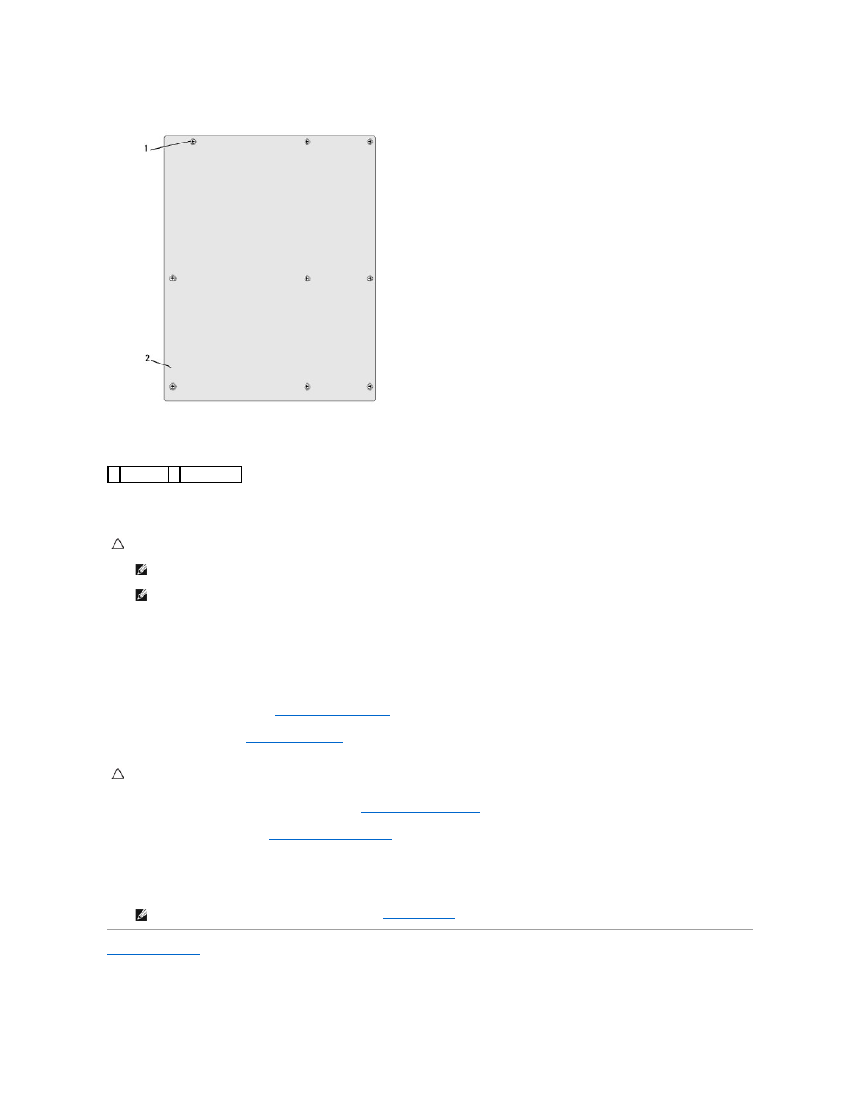
Remove the nine screws that secure the system board to the chassis.
10.
Lift the system board up and out.
11.
Orient the new or replacement system board by aligning the screw holes on the system board with the screw holes on the chassis.
12.
Replace the nine screws that secure the system board to the chassis.
13.
Connect the cables that you removed from the system board.
14.
Replace the memory modules (see
Replacing Memory Module(s)
).
15.
Replace the processor (see
Replacing the Processor
).
16.
Replace any expansion cards on the system board (see
Replacing a PCI Express Card
).
17.
Replace the computer cover (see
Replacing the Computer Cover
).
18.
Connect your computer and devices to electrical outlets, and turn them on.
19.
Flash the system BIOS, as needed.
Back to Contents Page
1 screws (9) 2 system board
CAUTION:
If you are replacing the system board, visually compare the replacement system board to the existing system board to ensure that you
have the correct part.
NOTE:
Some components and connectors on replacement system boards may be in different locations compared to the components and
connectors on the existing system board.
NOTE:
Jumper settings on replacement system boards are preset at the factory.
CAUTION:
Ensure that the heat sink assembly is correctly seated and secure.
NOTE:
For information on flashing the system BIOS, see
Flashing the BIOS
.