Power supply and wiring – Carrier 40RMS008-034 User Manual
Page 21
21
Power Supply and Wiring —
Check the unit data
plate to ensure that available power supply matches electrical
characteristics of the unit. Provide a disconnect switch of size
required to provide adequate fan motor starting current. See
Tables 4-6 for unit electrical data.
Install disconnect switch and power wiring in accordance
with all applicable local codes. See Fig. 15-17 and the unit
label diagram. For units with motor sizes less than 5 Hp
(3.7 kW), connect power wiring to unit with no. 10 ring termi-
nal. For units with motor sizes of 5 Hp (3.7 kW) or more, con-
nect power wiring with
1
/
4
-in. ring terminal.
The 40RM, 40RMQ and 40RMS size 007-016 units (except
40RM016 with YC or WD option) that have motors wired for
460-v, 3-ph, 60 Hz operation can be field-converted to
208/230-v, 3-ph, 60 Hz operation. Rewire the motor according
to the diagram plate on the motor. After reconfiguring the mo-
tor, mark the motor specifying 208-v or 230-v operation replac-
ing the 460-v sticker information on the units’ corner post.
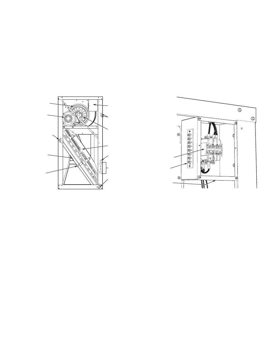
Fan motors are factory-installed on all units. Indoor-fan
contactors are located in the fan contactor box behind the side
access panel (see Fig. 15 and 16). Wire the thermostat to the
24-v control circuit terminal block located in the side of the fan
contactor control box, according to Fig. 17 or the unit label
diagram. If the air handler is part of a split system, complete the
wiring from the condensing unit to the thermostat shown in
Fig. 17.
2 3
2 2
2 1
1 3
1 2
1 1
1
0
5
°
C
6
00
V
R
J
A
W
FAN
CONTACTOR
24V
TERMINAL
BLOCK
POWER
WIRING
KNOCKOUT
Fig. 16 — Fan Contactor Box and Terminal Block
(Cover Removed) (Typical)
FILTER
ELEMENTS
FILTER
RETAINER
CLIP
FAN SCROLL
CONDENSATE
DRAIN
CONNECTION
(HORIZONTAL)
MOTOR
AND DRIVE
FAN
CONTACTOR
BOX
WIRE
ACCESS
COIL
FAN DRIVE
PULLEY
TXV BULB
ACCESS
REFRIGERANT/
CHILLED WATER
PIPING ACCESS
CONDENSATE
DRAIN
CONNNECTION
(VERTICAL)
LEGEND
TXV —
Thermostatic Expansion Valve
Fig. 15 — Wiring and Service Access
(Side Panel Removed)