Video connectors, Usb connectors, Guidelines – Dell PowerEdge 2650 User Manual
Page 7
Video Connectors
The system uses a 15-pin high-density D-subminiature connector on the front and back panels for attaching a VGA-compatible monitor to your system. The
video circuitry on the system board synchronizes the signals that drive the red, green, and blue electron guns in the monitor.
Guidelines
l
This system provides two video connectors, one on the back panel, and one on the front panel. If the monitor is connected to the front-panel video
connector, the back-panel video connector is disabled.
l
The keyboard and mouse must be connected to the same panel as the monitor. For example, if the monitor is connected to the front-panel video
connector, the keyboard and mouse must also be connected to the keyboard/mouse front-panel connector. This connector is a PS/2 connector and the
keyboard connection is the default. To use both the keyboard and mouse from the front-panel connector, you must use a Y-cable.
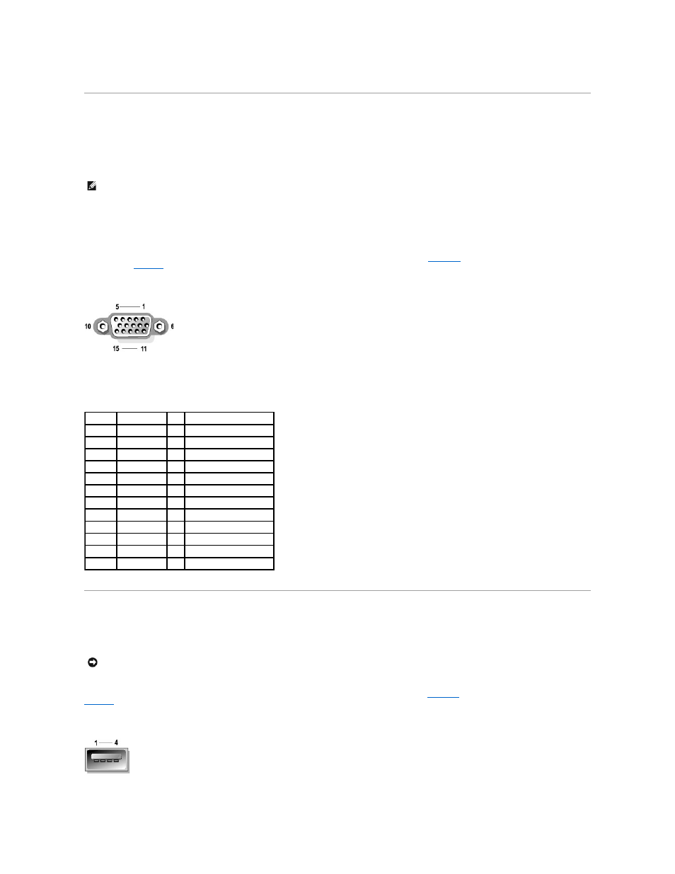
illustrates the pin numbers for the video
defines the pin assignments and interface signals for the video connector.
Figure B-6. Pin Numbers for the Video Connector
USB Connectors
Your system contains a single USB connector on the front control panel, and two USB connectors on the rear panel for attaching USB-compliant devices. USB
devices are typically peripherals such as mice, keyboards, and system speakers.
If you reconfigure your hardware, you may need pin number and signal information for the USB connectors.
illustrates the USB connector and
defines the pin assignments and interface signals for the USB connector.
Figure B-7. Pin Numbers for the USB Connector
NOTE:
When a monitor is connected to the front panel, the back-panel keyboard, mouse, and video are all disabled.
Table B-5. Video Connector Pin Assignments
Pin
Signal
I/O Definition
1
RED
O
Red video
2
GREEN
O
Green video
3
BLUE
O
Blue video
4
NC
N/A No connection
5–8, 10 GND
N/A Signal ground
9
VCC
N/A Vcc
11
NC
N/A No connection
12
DDC data out O
Monitor detect data
13
HSYNC
O
Horizontal synchronization
14
VSYNC
O
Vertical synchronization
15
DDC clock out
O
Monitor detect clock
Shell
N/A
N/A Chassis ground
NOTICE:
Do not attach a USB device or a combination of USB devices that draw a maximum current over 500 mA per channel on +5 V. Attaching devices
that exceed this threshold may cause the USB ports to shut down. See the documentation that accompanied the USB devices for their maximum current
ratings.