Mouse connector – Dell PowerEdge 2650 User Manual
Page 6
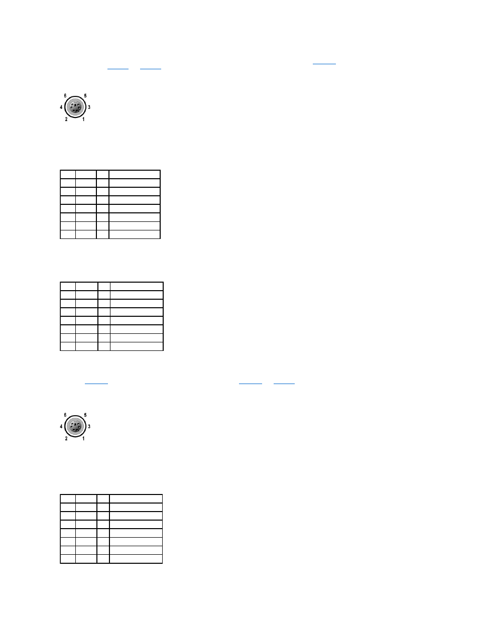
illustrates the pin numbers for the
and
defines the pin assignments and interface signals for the keyboard connector.
Figure B-4. Pin Numbers for the Keyboard Connector
Mouse Connector
The following is pin information for the mouse connector. If you reconfigure your hardware, you may need pin number and signal information for the mouse
connector.
and illustrates the pin numbers for the mouse connector.
defines the pin assignments and interface signals for
the mouse connector.
Figure B-5. Pin Numbers for the Mouse Connector
Table B-2. Keyboard Connector Pin
Assignments (Back Panel)
Pin
Signal
I/O Definition
1
KBDATA I/O Keyboard data
2
NC
N/A No connection
3
GND
N/A Signal ground
4
FVcc
N/A Fused supply voltage
5
KBCLK
I/O Keyboard clock
6
NC
N/A No connection
Shell N/A
N/A Chassis ground
Table B-3. Keyboard/Mouse
Combination Connector
Pin Assignments (Front Panel)
Pin
Signal
I/O Definition
1
KBDATA
I/O Keyboard data
2
MSDATA I/O Mouse data
3
GND
N/A Signal ground
4
FVcc
N/A Fused supply voltage
5
KBCLK
I/O Keyboard clock
6
MSCLK
I/O Mouse clock
Shell N/A
N/A Chassis ground
Table B-4. Mouse Connector Pin
Assignments (Back Panel)
Pin
Signal
I/O Definition
1
MSDATA I/O Mouse data
2
NC
N/A No connection
3
GND
N/A Signal ground
4
FVcc
N/A Fused supply voltage
5
MSCLK
I/O Mouse clock
6
NC
N/A No connection
Shell N/A
N/A Chassis ground