Installing a drive in a 5.25-inch drive bay – Dell OptiPlex GX1p User Manual
Page 11
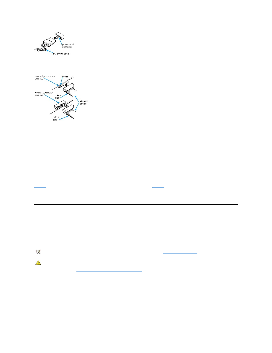
The drive's interface connector is a card-edge connector or a header connector, as shown in Figure 5.
Figure 5. Drive Interface Connectors
When attaching the interface cable to a drive, be sure to match the colored strip on the cable to pin 1 of the drive's interface connector. For the
location of pin 1 on the drive's interface connector, see the documentation that came with the drive.
When disconnecting an interface cable from the system board, be sure to press in on the locking tabs on the cable connector before disconnecting
the cable. When attaching an interface cable to the system board, be sure that the locking tabs snap into place, ensuring that the cable is firmly
attached to the connector on the system board.
Most interface connectors are keyed for correct insertion; that is, a notch or a missing pin on one connector matches a tab or a filled-in hole on the
other connector (see
). Keying ensures that the pin-1 wire in the cable (indicated by the colored strip along one edge of the cable) goes to
the pin-1 end of the connector.
The pin-1 end of a card-edge connector is usually identified by a notch cut about a quarter of an inch from the end of the connector, as shown in
. A header connector is usually keyed by the omission of one of its pins (see
), with the corresponding hole filled in on the
connector cable.
The pin-1 end of a connector on a board or a card is usually indicated by a silk-screened "1" printed directly on the board or card.
Installing a Drive in a 5.25-Inch Drive Bay
The 5.25-inch drive bays can accommodate any of the following types of drives:
l
A diskette drive or tape drive that uses the diskette/tape drive interface on the system board
l
A CD-ROM or tape drive that uses an EIDE interface on the system board
l
A CD-ROM or tape drive that uses its own controller card
To install a drive in a 5.25-inch drive bay, follow these steps.
1. Unpack the drive and prepare it for installation.
Check the documentation that accompanied the drive to verify that the drive is configured for your computer system. Change any settings
necessary for your configuration.
NOTICE: When connecting an interface cable, do not reverse the interface cable (do not place the colored strip away from pin 1 of
the connector). Reversing the cable prevents the drive from operating and could damage the controller, the drive, or both.
NOTE: For information on configuring, connecting, and installing SCSI drives, see "
CAUTION: To avoid the possibility of electric shock, turn off the computer and any peripherals, disconnect them from their
electrical outlets, and then wait at least 5 seconds before you remove the computer cover. Also, before you install an
expansion card, see "
Safety First
— For You and Your Computer
."
NOTICE: When you unpack the drive, do not set it on a hard surface, which may damage the drive. Instead, set the drive on a
surface, such as a foam pad, that will sufficiently cushion it.