Installing the power supply – Dell PowerEdge SC 430 User Manual
Page 43
4.
Disconnect the following power-supply cables:
l
P1 and P2 connector to the system board
l
P3 and P5 connectors to the SATA drives (if applicable)
l
P11 connector to the SCSI drives (if applicable)
l
P7 connector to the diskette drive (if applicable)
l
P8 and P9 connectors to the optical and tape drives (if applicable)
5.
Remove the IDE, I/O panel, and SATA cables attached to the routing clamps on the side of the power supply.
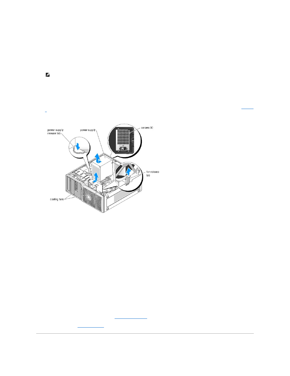
6.
Using a #2 Phillips screwdriver, remove the four Phillips screws that secure the power supply to the back panel.
7.
Figure 5-5. Removing the Power Supply and Cooling Fan
Installing the Power Supply
1.
Prepare the new power supply for installation.
2.
Align the power supply mounting holes with the mounting holes on the back panel.
3.
Slide the power supply toward the back panel until it snaps into place over the power-supply release tab.
4.
Using a #2 Phillips screwdriver, install the four Phillips screws that secure the power supply to the back panel.
5.
Reconnect the following power-supply cables:
l
P1 and P2 connector to the system board
l
P3 and P5 connectors to the SATA drives (if applicable)
l
P11 connector to the SCSI drives (if applicable)
l
P7 connector to the diskette drive (if applicable)
l
P8 and P9 connectors to the optical and tape drives (if applicable)
6.
Reinstall the heat sink and shroud assembly. See "
."
7.
Close the system. See "
Closing the System
" in "Troubleshooting Your System."
NOTE:
Note the routing of the DC power cables underneath the tabs in the system frame as you release the tabs and remove the cables from the
system board and drives. You must route these cables properly when you replace them to prevent their being pinched or crimped.