Removing and replacing the front drive bezel – Dell PowerEdge SC 430 User Manual
Page 25
The system board can accommodate one processor, five expansion cards (two 5-V, half-length 32-bit, 33-MHz PCI, one 2.5-Gb/sec PCIe [x1], one 2.5-Gb/sec
PCIe [x4], and one 2.5-Gb/sec PCIe [x8]), and four 533-MHz unbuffered ECC DDR II single or dual-rank memory modules.
The drive bays provide space for up to two 1-inch SATA hard drives with the integrated SATA controller or two SCSI hard drives. The SCSI hard drives must be
connected to a controller card. They also provide space for an optional optical and diskette drive, or an optional tape backup unit (TBU). Power is supplied to
the system board and internal peripherals through a single nonredundant power supply.
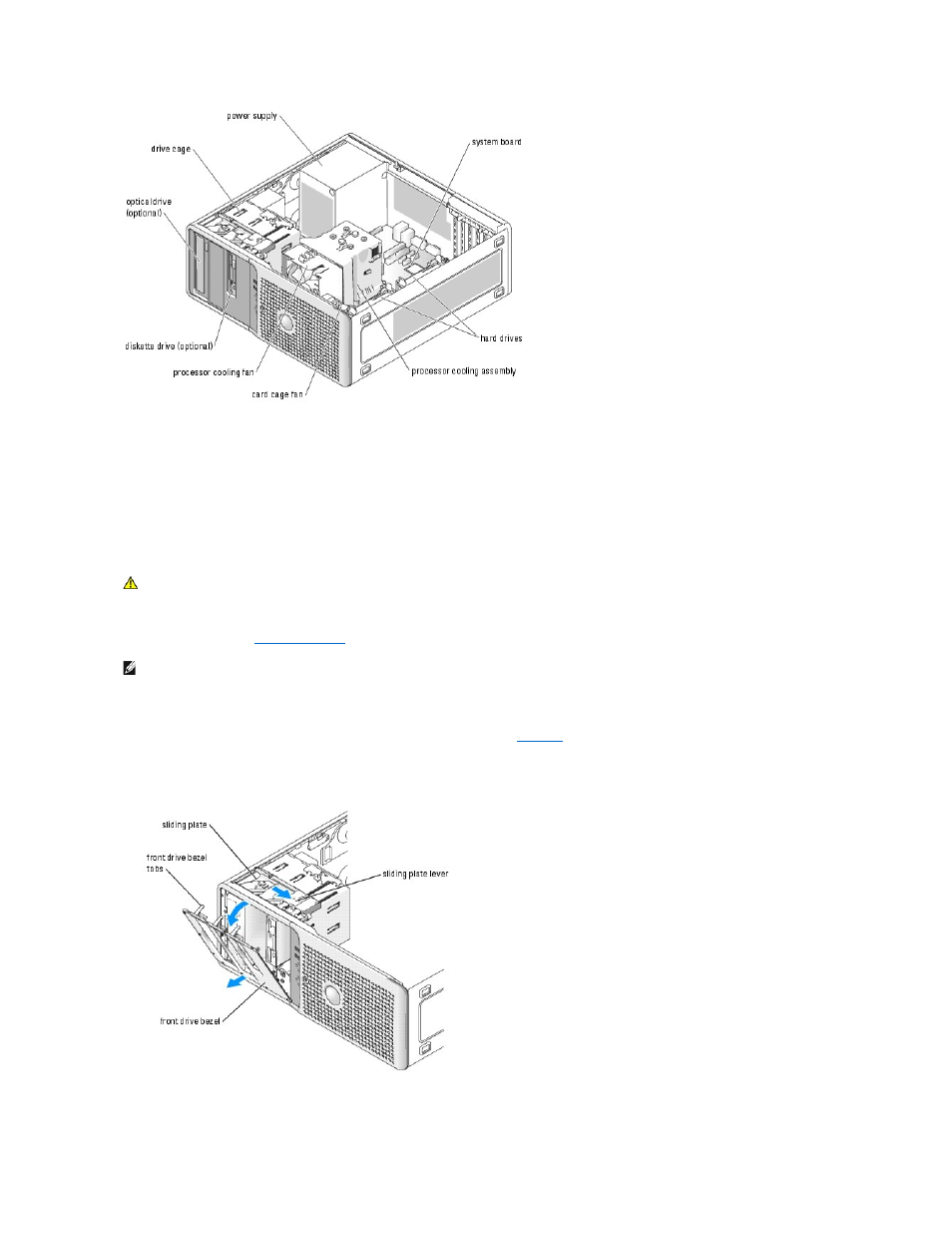
Removing and Replacing the Front Drive Bezel
1.
Open the system. See "
2.
Pull the lever on the sliding plate to the right until it releases the front drive bezel from its side hinges.
3.
Carefully tilt the front drive bezel away from the chassis and lift it out as shown in
4.
To replace the front drive bezel, reverse the steps above and snap the bezel into place.
Figure 4-3. Removing and Replacing the Front Drive Bezel
CAUTION:
Only trained service technicians are authorized to remove the system cover and access any of the components inside the system.
Before performing any procedure, see your Product Information Guide for complete information about safety precautions, working inside the
computer and protecting against electrostatic discharge.
NOTE:
This sliding plate secures and releases the drive bezel and helps to secure the drives.