Figure 4) – Dell PowerVault 715N (Rackmount NAS Appliance) User Manual
Page 35
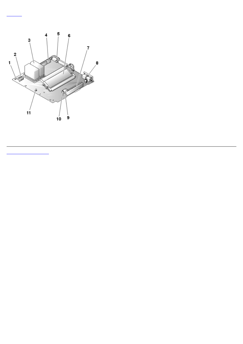
defines the system board features, including switches, connectors, and labels located on the system board. The
system board labels are in parentheses.
Figure 4. System Board Features
1 Fan power connector (CPUFAN1)
2 DIP switch (SW3)
3 Microprocessor and heat sink (CPU)
4 Power supply connectors (CN1 and CN2)
5 Serial port connector (COM1)
6 Memory modules (DIMM1 and DIMM2)
7 PCI riser card slot (PCI1)
8 LAN connectors (LAN1 and LAN2)
9 Battery connector (BT1)
10 Clear CMOS jumper (JP1)
11 System version jumper (JP5)
See also other documents in the category Dell Computer hardware:
- PowerEdge RAID Controller H700 (56 pages)
- PowerEdge RAID Controller H700 (200 pages)
- PowerEdge RAID Controller H700 (178 pages)
- PowerVault 110T DLT VS80 (Tape Drive) (49 pages)
- PowerVault TL2000 (22 pages)
- PowerVault TL4000 (306 pages)
- PowerVault TL2000 (2 pages)
- PowerVault TL4000 (2 pages)
- PowerVault TL2000 (176 pages)
- PowerVault TL2000 (16 pages)
- PowerVault TL2000 (3 pages)
- PowerVault TL2000 (116 pages)
- PowerVault 130T DLT (Tape Library) (49 pages)
- PowerVault TL2000 (1 page)
- PowerEdge 800 (82 pages)
- PowerEdge 800 (2 pages)
- PowerEdge 800 (27 pages)
- PowerEdge 800 (28 pages)
- PowerEdge 800 (58 pages)
- PowerEdge 800 (87 pages)
- PowerEdge 800 (24 pages)
- PowerEdge 6400 (86 pages)
- PowerVault 124T (57 pages)
- PowerVault 110T LTO (Tape Drive) (28 pages)
- PowerVault 124T (55 pages)
- PowerVault 124T (73 pages)
- PowerVault 124T (65 pages)
- PowerVault 124T (4 pages)
- PowerVault 124T (79 pages)
- PowerVault 124T (2 pages)
- PowerVault 124T (64 pages)
- PowerVault 124T (56 pages)
- PowerVault 124T (66 pages)
- PowerVault TL4000 (1 page)
- PowerVault TL4000 (66 pages)
- PowerVault TL4000 (22 pages)
- PowerVault TL4000 (3 pages)
- PowerVault TL4000 (176 pages)
- PowerVault TL4000 (2 pages)
- PowerVault TL4000 (16 pages)
- PowerVault TL4000 (116 pages)
- PowerEdge RAID Controller 6i (120 pages)
- PowerEdge RAID Controller 6i (156 pages)
- PowerVault 715N (Rackmount NAS Appliance) (86 pages)
- PowerVault 715N (Rackmount NAS Appliance) (132 pages)