System board jumpers, System board features – Dell PowerVault 715N (Rackmount NAS Appliance) User Manual
Page 34
Each of the switches has two positions or settings (usually on and off). To change the setting of a slide switch, use a small
pointed object such as a small screwdriver or a straightened paper clip to slide the switch to the proper position. To
change the setting of a rocker switch, use the screwdriver or paper clip to press down on the appropriate side of the
switch. In either case, do not use a pen, pencil, or other object that might leave a residue on the switch.
System Board Jumpers
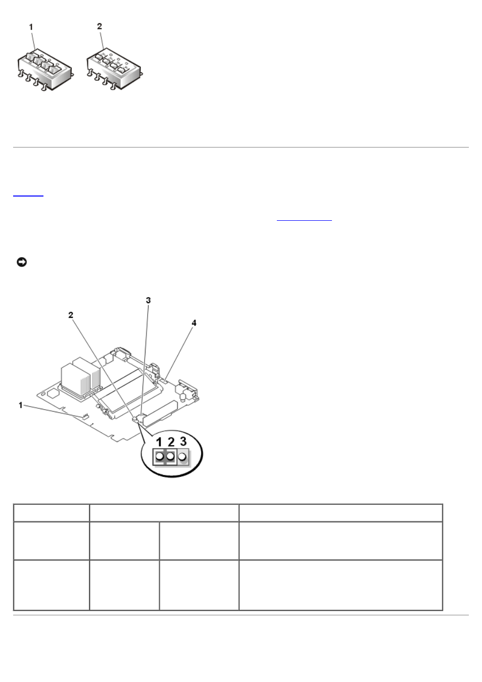
shows the location of the Clear CMOS jumper and the system version jumper on the system board. Table 1 lists
the jumper setting information.
For instructions on using the Clear CMOS jumper to clear CMOS, see "
Earlier systems with a system version number of SN1A have the JP5 jumper set on pins 1 and 2. Later systems with a
system version number of SN1B have the JP5 jumper set on pins 2 and 3. Do not change these jumper settings.
NOTICE:
All DIP switch (SW3) positions must remain in the OFF position. Do not change these DIP switch settings.
Figure 3. System Board Jumpers
1 System version jumper (JP5)
2 Clear CMOS jumper (JP1)
3 Battery
4 System version number label (SN1A = early
system; SN1B = later system)
Table 1. System-Board Jumper Settings
Jumper
Setting
Description
Clear CMOS
(JP1)
pins 1-2
(pins 2-3)
(default)
The password feature is enabled.
The password feature is disabled.
System version
jumper (JP5)
pins 1-2
pins 2-3
(default for
early systems)
(default for
later systems)
Use in this position for early system boards with a
version number of SN1A (do not change).
Use in this position for later system boards with a
version number of SN1B (do not change).
System Board Features