Power supply, Power input connectors (cn1 and cn2), System board features – Dell PowerVault 715N (Rackmount NAS Appliance) User Manual
Page 22
9.
10. Install the
11.
.
12.
.
13.
.
14. Reconnect any external peripheral cables that you disconnected from their connectors at the back of the system.
15. Connect the power to the system and turn on the system.
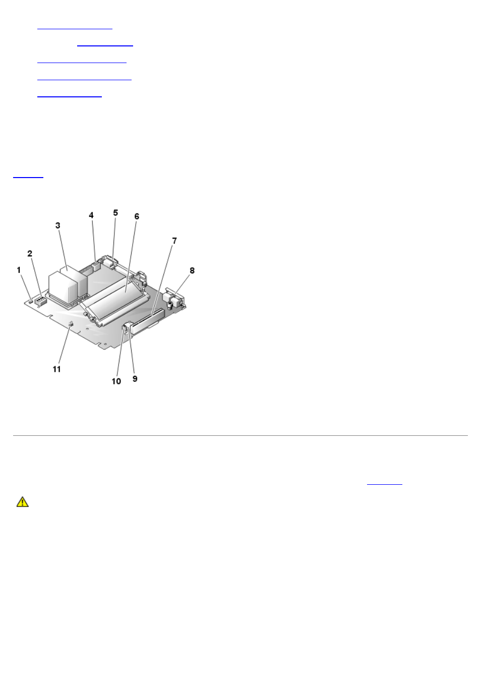
System Board Features
defines the system board features. The system board labels are in parentheses. Refer to this figure when
replacing your system board or components that attach to the system board.
Figure 9. System Board Features
1 Fan power connector (CPUFAN1)
2 DIP switch (SW3)
3 Microprocessor and heat sink (CPU)
4 Power supply connectors (CN1 and CN2)
5 Serial port connector (COM1)
6 Memory modules (DIMM1 and DIMM2)
7 PCI riser card slot (PCI1)
8 LAN connectors (LAN1 and LAN2)
9 Battery connector (BT1)
10 Clear CMOS jumper (JP1)
11 System version jumper (JP5)
Power Supply
Your system has a single power supply, which is secured by a locking tab and four screws (see
CAUTION:
Read the safety instructions in your System Information document.
Figure 10. Power Supply Removal
1 Locking tab
2 Power supply
3 Screws (4)