Canon GM-1000 User Manual
Page 75
CANON Digital Galvano Scanner System GM-1000 Series
Users Manual 1.20
75
Input the external trigger signal
The external trigger signal is input from the digital I/O connector.
(See 5-1 ‘Connector Pin Arrangement)
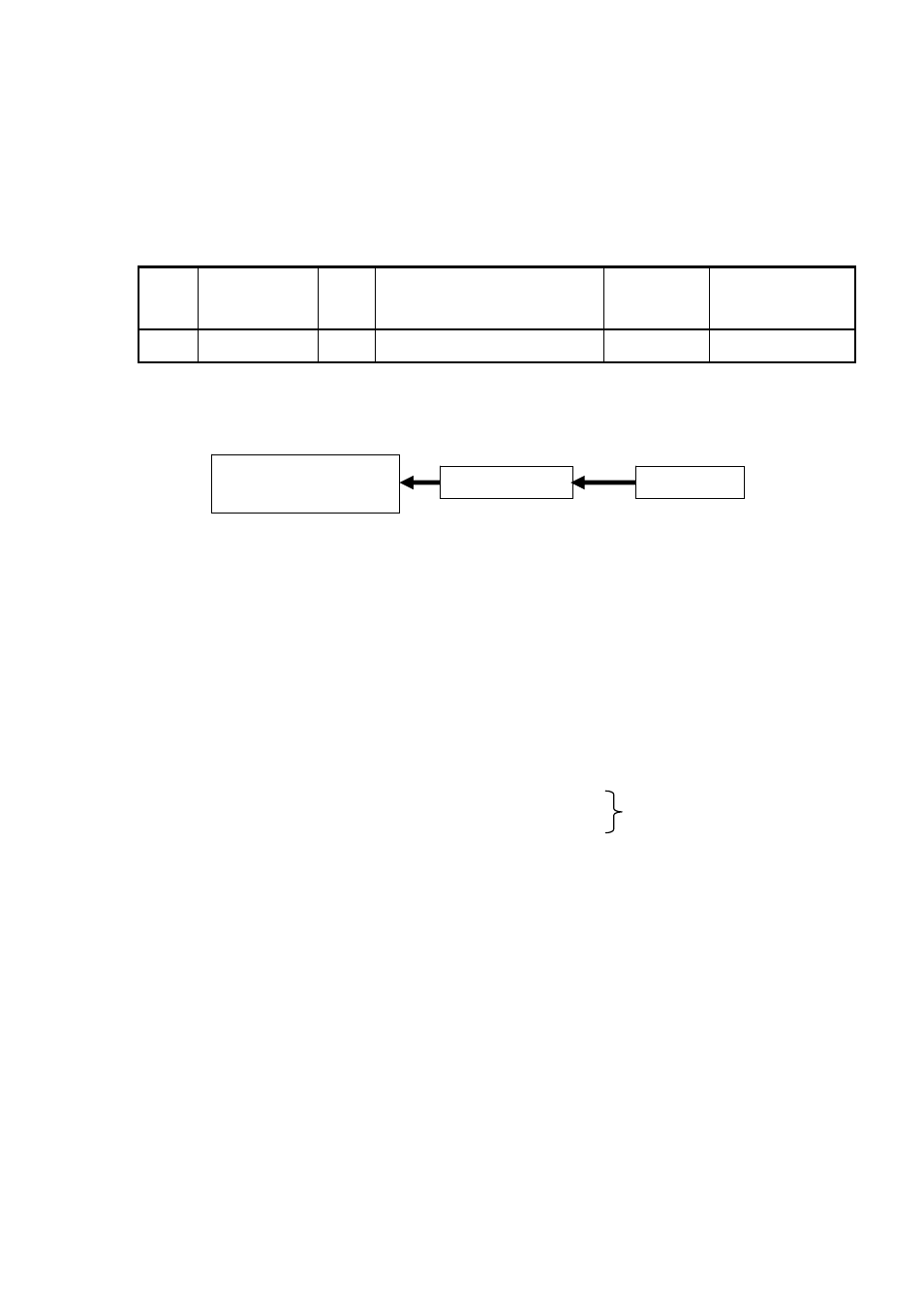
Connector pin arrangement
Pin
No.
Monitor Board
Signal Name
I/O Signal
Description Logic Remarks
B5
D
10 Input
External
Trigger
Signal
High: ON
See Circuit below.
Connection Specifications
3.3V TTL Input
Operation procedure
(Raster Scan Parameter Settings)
・
Set Parameter ID =26
Raster Scan Time
Setting
・
Set Parameter ID =27
Raster Scan Duty Ratio
Setting
・
Set Parameter ID =28
Raster Scan Angle
Setting
(Raster Scan Operation)
・
Send Command ID=8
Data=6 Movement Start
(Movement to the initial position
of
a
raster
scan)
・
Send Command ID=23 Data=8 (One way scan)
Data=9 (One coming and going)
(Reference: Data = 3 in case of continuous operation)
・
Input the external trigger Signal
・
Send Command ID=23
Data=0 Scan Stop
Notes
・
The external trigger input during raster scan move is ignored.
・
From the external trigger signal input, until the time actual operation starts, there can be a
fluctuation of up to a maximum of 10 usec.
FPGA
3.3V-TTL
R : 100Ω
Connector
Select either