Baumer ISI33 counter User Manual
Page 9
en
gl
is
h
www.baumer.com
9
ISI30, ISI31, ISI32, ISI33
Main technical features:
Display:
LCD, 8 decades, height of the figures 8 mm.
Display range:
-9999999 ... 99999999
with leading zeros suppression.
Overflow:
In case of a display range overflow, the
counter starts again from 0, but without
removing the leading zeros and activating
all decimal points.
In case of a display range underflow, the
counter starts again from 0 and displays
the minus sign, without removing the lead-
ing zeros and activating all decimal points.
Keys:
Electrical locking of the reset key
Housing:
Panel mounting, 48 x 24 mm
according to DIN 43 700, RAL 7021
Panel cut-out:
22,2
+0,3
x 45
+0,6
mm
Mounting depth:
approximately 48 mm
Weight:
approximately 50 g
Protection level:
IP65 on the front side
Connection:
Screw terminals, RM 5.00, 8 poles
Rated cross-section: max.: 1 x 1,5 mm
2
2 x 0,75 mm
2
AWG 26-14
Connection diameter:
0,4 ... 2,3 mm single-wire
AWG 28-12
EMC:
Interference emissions EN55011 Class B
Interference resistance EN 61000-6-2
Device safety:
Design to:
EN61010 Part 1
Protection Class:
2
Application area:
Soiling Level 2
Low Voltage Directive (for the AC models):
EN 61010 Part 1 ; overvoltage category 2,
contamination level 2
Power supply:
Non-replaceable lithium battery
(lifetime approximately, 8 years at 20°C)
Working temperature:
–10 ... +55 °C, relative humidity < 85%,
without condensation
Operating temperature:
–10 ... +60 °C
Storage temperature:
–20 ... +70°C
Altitude:
to 2000 m
Backlighting:
external electrical source
(24 V DC ±20 %, 50 mA)
Screw terminals 1 and 2:
Function and max. frequences (Pulse/Pause 1:1)
see Table 2
NPN :
active for negative edge
Input resistance:
approximately 1 MOhm
Low level:
0 ... 0,7 V DC
High level:
3 ... 30 V DC
PNP :
active for positive edge
Input resistance:
approximately. 100 kOhm
Low level:
0 .. 0,7 V DC
High level:
4 .. 30 V DC
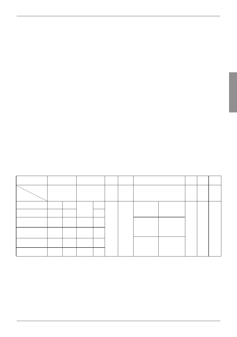
Input specification, pin assignment and adjustable operating modes (DC versions).
A control input (screw terminal 5) allows adjusting the operating mode.
Screw terminal
Nr. 1
Nr. 2
Nr. 3
Nr. 4
Nr. 5
Nr. 6
Nr. 7
not active
=
adding
contact with
GND =
subtracting
ISI30.010AX01
ISI30.012AX01
ISI31.010AX01
ISI31.011AX01
ISI33.010AX01
ISI33.011AX01
7 kHz
12 kHz
7 kHz
12 kHz
3 kHz
6 kHz
NPN
NPN
PNP
NPN
PNP
30 Hz
NPN
NPN
7 kHz
12 kHz
3 kHz
6 kHz
NPN
PNP
NPN
PNP
N
PN
r
es
et
i
np
ut
N
PN
r
es
et
k
ey
lo
ck
in
g
in
pu
t,
C
on
ta
ct
w
ith
G
N
D
, k
ey
f
re
e.
.
not active
=
Cnt.Dr Mode
contact with
GND =
Up.Dn Mode
not active
=
Quad Mode
contact with
GND =
Quad2 Mode
G
N
D
=
0
V
D
C
B
ac
kl
ig
ht
in
g
(–
)
Designation
Model
INP A
INP B
Reset
Reset
Enable
Control inputs for operating
mode (Mode)
GND
BL
–
Nr. 8
BL
+
B
ac
kl
ig
ht
in
g
(+
)
PNP
Table 2