Baumer ISI33 counter User Manual
Page 10
10
www.baumer.com
ISI30, ISI31, ISI32, ISI33
Screw terminal 3:
Reset input, active for negative edge Contact input / Open
Collector NPN (switching at 0 V DC)
Low level:
0 ... 0,7 V DC
High level:
3 ... 30 V DC
Min. pulse duration:
50 ms
Input resistance:
approximately 2,2 MOhm
Screw terminal 5:
Operating mode switch (Mode) Contact input / Open Collector
NPN (switching at 0 V DC)
Low level:
0 ... 0,7 V DC
High level:
3 ... 5 V DC
Input resistance:
approximately 2,2 MOhm
Function:
see Table 2
Screw terminal 4:
Electrical locking of the reset key Contact input / Open Collector
NPN (switching at 0 V DC)
Low level:
0 ... 0,7 V DC
High level:
3 ... 5 V DC
Input resistance:
approximately. 2,2 MOhm
Input not active:
Reset key locked
Input in contact
with GND:
Reset key unlocked
Screw terminal 6:
GND connection common for all inputs
Screw terminal 7:
(–) external power supply for the LCD backlight option
Screw terminal 8:
(+) external power supply for the LCD backlight option
(24 V DC ±20%, 50 mA)
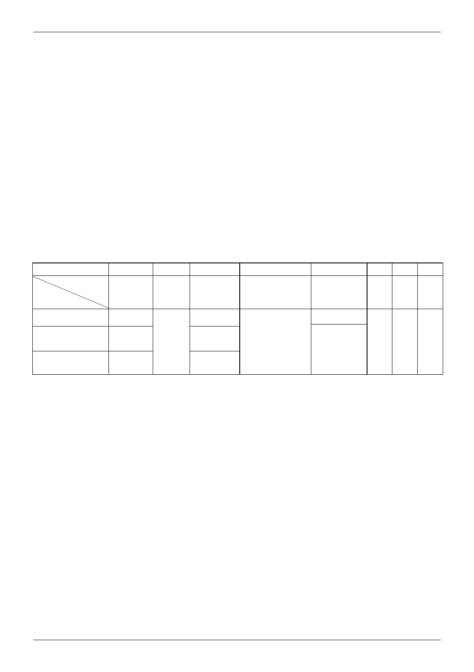
Input specification and pin assignment (AC-version)
Screw terminal
No. 1
INP A
AC/DC
No. 2
No. 3
INP B AC/DC
No. 4
No 5
No. 6
No. 7
No. 8
ISI30.013AX01
ISI31.013AX01
ISI32.013AX01
counting
C
om
m
on
c
on
ne
c-
ti
on
f
or
I
N
P
A
a
nd
IN
P
B
Reset Enable
NPN reset key lok-
king input, Contact
with GND. key free.
not connected
NPN reset input
G
N
D
=
0
V
D
C
B
ac
kl
ig
ht
in
g
(–
)
B
ac
kl
ig
ht
in
g
(+
)
Screw terminals 1 and 3:
Function:
see Table 3
Optocoupler input 10 ... 260 V AC/V DC
galvanic isolation, active for high signal
Min. pulse duration: 16 ms
Max frequency:
approximately 30 Hz
Low level:
0 ... 2 V AC/V DC
High level:
10 ... 260 V AC/V DC
Input resistance:
approximately 160 kOhm
Screw terminal 2:
Common AC/DC, common connection for the optocoupler inputs
(screw terminals 1 and 3).
Screw terminal 4:
Electrical locking of the reset key Contact input / Open
Collector NPN (switching at 0 V DC)
Low level:
0 ... 0,7 V DC
High level:
3 ... 5 V DC
Input resistance:
approximately 2,2 MOhm
Input not active:
Reset key locked
Input in contact with GND:
Reset key unlocked
Screw terminal 5:
Function: see table 3, active for negative edge Contact input
/ Open Collector NPN (switching at 0 V DC)
Low level:
0 ... 0,7 V DC
High level:
3 ... 5 V DC
Min. pulse duration:
50 ms
Input resistance:
approximately 2,2 MOhm
Input high:
- - -
Input low :
Reset of the counter
Dynamic resetting behaviour
Screw terminal 6:
Common GND connection for screw terminal 4 (reset key
locking input) and screw terminal 5 (reset input).
Screw terminal 7:
(–) external power supply for the backlight option
Screw terminal 8:
(+) external power supply for the backlight option
(24 V ±20%, 50 mA)
Designation
Model
Common
AC/DC
Reset
GND
BL
–
BL
+
adding
subtracting
counting
direction
reset
counting
Table 3