Ethernet/cresnet interface crestron cen-cn, Physical description, Cen-cn ports – Crestron electronic CEN-CN User Manual
Page 6: Cen-cn physical views, Cen-cn rear panel
Ethernet/Cresnet Interface Crestron CEN-CN
2
••
Ethernet/Cresnet Interface: CEN-CN
Operations Guide - DOC. 5721
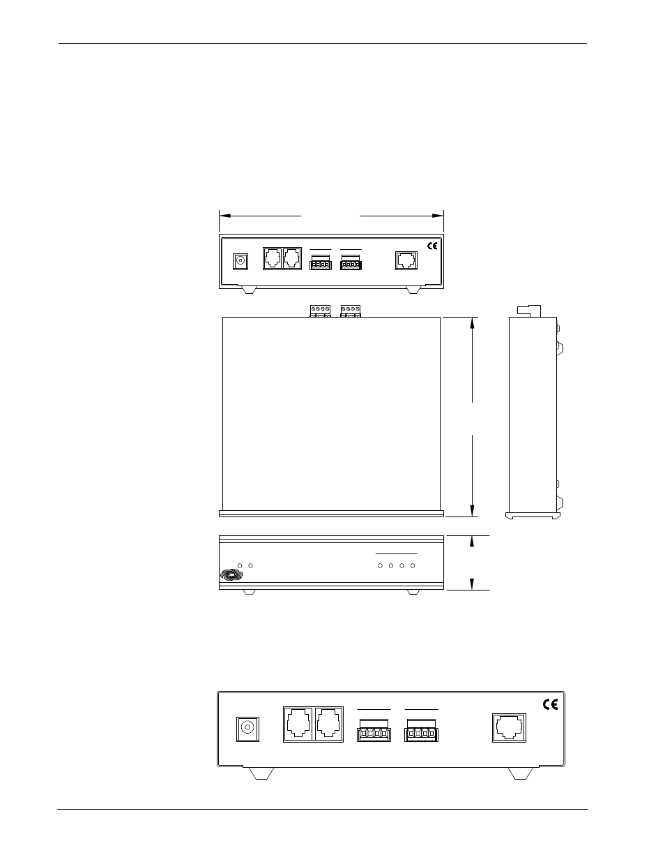
Physical Description
The CEN-CN, shown below, is housed in a black enclosure with silk-screened labels
on the front and rear panels. On the front panel are six light-emitting diodes (LEDs)
for indicating the status of the unit, the attached device(s), and the connected
Ethernet. All connections are made through on the rear panel ports, a Crestron
6-conductor modular cable and two 4-pin connector plugs are provided. There are
four rubber feet on the base of the unit for stability and to prevent slippage.
CEN-CN Physical Views
ETHERNET
TXD
NET
PWR
RXD
ERR
LNK
CRESTRON
CRESTRON
ETHERNET/CRESNET INTERFACE
ETHERNET/CRESNET INTERFACE
CEN-CN
CEN-CN
CRESTRON ELECTRONICS INC. ROCKLEIGH, N.J. 07647 USA
CRESTRON ELECTRONICS INC. ROCKLEIGH, N.J. 07647 USA
12VDC
.5A
ETHERNET
P C
NET
Y
NET
24
G
Z
Z G
Y
24
NET
6.32 in
(16.06 cm)
1.70 in
(4.32 cm)
7.07 in
(17.95 cm)
CEN-CN Ports
Each CEN-CN rear panel port has a silk-screened label. For the descriptions of the
ports, refer to the diagram below and following paragraphs.
CEN-CN Rear Panel
CRESTRON ELECTRONICS INC. ROCKLEIGH, N.J. 07647 USA
CRESTRON ELECTRONICS INC. ROCKLEIGH, N.J. 07647 USA
12VDC
.5A
ETHERNET
P C
N E T
Y
N E T
2 4
G
Z
Z G
Y
2 4
N E T