Ethernet/cresnet interface crestron cen-cn, Communication via pc port of cen-cn – Crestron electronic CEN-CN User Manual
Page 12
Ethernet/Cresnet Interface Crestron CEN-CN
8
••
Ethernet/Cresnet Interface: CEN-CN
Operations Guide - DOC. 5721
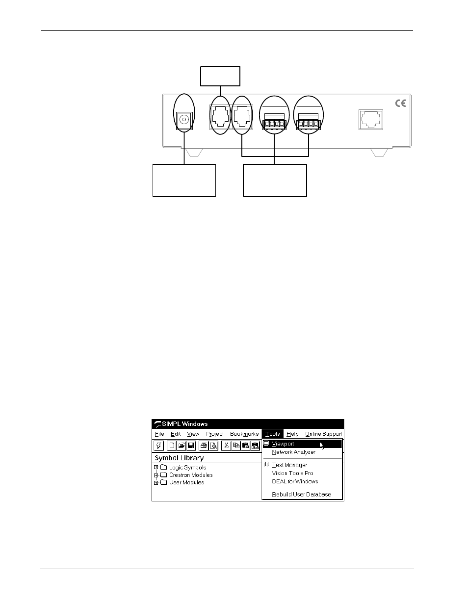
Typical Connections When Configuring the CEN-CN
CRESTRON ELECTRONICS INC. ROCKLEIGH, N.J. 07647 USA
CRESTRON ELECTRONICS INC. ROCKLEIGH, N.J. 07647 USA
12VDC
.5A
ETHERNET
P C
NET
Y
NET
2 4
G
Z
Z G
Y
2 4
NET
FROM EXTERNAL
AC POWER PACK
TO PC
COM PORT
(NOT REQUIRED IF OPERATING
POWER IS SUPPLIED
VIA CRESNET WIRING)
TO CRESNET
NETWORK WIRING
(NOT REQUIRED IF OPERATING
POWER IS SUPPLIED VIA
EXTERNAL AC POWER PACK)
1. If a CEN-CN to PC cable is fabricated, proceed to the next step.
Attach one end of the 6-conductor modular cable to the RJ11 to DB9F
adapter.
2. Attach the RJ11 connector to the PC port of the CEN-CN.
3. Attach the DB9 connector to an available COM port on the PC.
Communication via PC Port of CEN-CN
Before performing this procedure, refer to “Obtaining Communications” on page 7
for cabling instructions.
1. Make sure that no programs accessing the COM port of the PC are
running.
2. Select Start | Programs | Crestron | SIMPL Windows to start SIMPL
Windows.
3. SIMPL Windows responds with an opening splash screen and may
display the “What do you want to do?” dialog box. If so, close the
dialog box.
4. As shown below, select Tools | Viewport to open the Crestron
Viewport dialog box.
Accessing the Viewport