3 geogauge applications – Humboldt H-4140 GeoGauge User Manual
Page 5
5
Many current methods of measuring material modulus or lift stiffness in the
field require large forces to produce a measurable deflection. The GeoGauge
uses technology borrowed from the military to measure very small deflections,
allowing much smaller loads. The GeoGauge does not measure the deflection
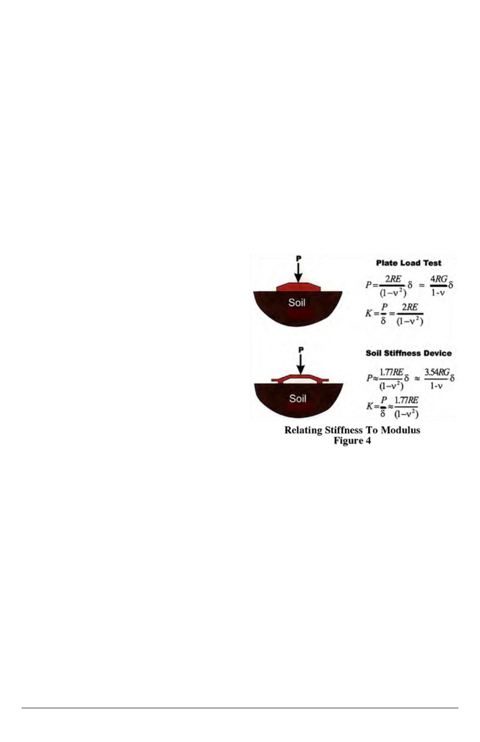
resulting from the GeoGauge weight. Rather, the GeoGauge vibrates, producing
small changes in force that produce small deflections. The material deflects an
amount δ, which is proportional to the outside radius of the ring foot (R), the
Young’s modulus (E), the shear modulus (G) and Poisson’s ratio (υ) of the soil
1
.
The stiffness is the ratio of the force to displacement: K=P/δ. The GeoGauge
produces soil stress and strain levels common for pavement, bedding and
foundation applications (27.58 kPa or ~ 4 psi). Young's and shear modulus can
be determined from GeoGauge measurements if a Poisson's ratio is
assumed (Fig. 4).
GeoGauge measurements intentionally mimic Resilient Modulus measurements
as much as typical site conditions
will allow. This allows GeoGauge
measurements to be related to
Resilient Modulus.
1.3: GeoGauge
®
Applications
The GeoGauge has an application
anywhere there is a need to structurally
evaluate a construction material in-
place. Following are some examples.
The GeoGauge is better suited for the
in-place QC of unbound materials than
any other available instrument for:
• In-place estimates of Resilient
Modulus
• Modulus measurements that relate well to relative compaction
• Identifying structural anomalies
• Quantifying strength gain with time
• Obtaining precise measurements
This is based on the findings of the Transportation Research Board’s National
Cooperative Research Program Project 10-65.
The GeoGauge can be used in the QC of compacted subgrades and bases. The
QC method utilizes a control strip and initially established target stiffness values
that are related to conventional relative compaction. Ultimately, target stiffness
values are related to design values and expected values based on experience
(e.g., Resilient Modulus). Appendix 1 is a case study of such a QC method.
1 Poulos, H.G., and Davis, E.H., Elastic Solutions For Soil & Rock Mechanics, 1974, page 167-168.