Install control arm weldments, Install adc/nta907/3007hd arms – Great Plains VARIABLE RATE KIT Operator Manual User Manual
Page 8
8
Air Drill Variable Rate Kit
Great Plains Mfg., Inc.
166-263M
6/23/2010
Install Control Arm Weldments
Install ADC/NTA907/3007HD Arms
For NTA607/2007HD, continue at step 37.
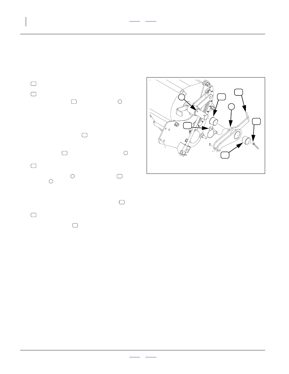
Refer to Figure 10
29. Select one new:
168-370H ELECTRONIC CONTROL ARM WLDMNT
and two new:
890-202C
GAUGE WHEEL SFT PIVOT BUSHING
30. Press one bushing
into the inside end
of the
control arm tube (the side with the longer arm with
indicator point).
Using the existing
1
⁄
4
in holes in the tube as a guide,
drill a
1
⁄
4
in hole through both sides of the bushing.
31. Press the other bushing
into the outside end of
the control arm tube.
32. With indicator tip to rear, and toward gearbox, place
arm weldment
assembly on control shaft
.
33. Select one saved:
805-065C PIN WIRE RETAINING 1/4 X 1 3/4
Align the arm tube
and inside bushing
with
the hole
in the gearbox control shaft. The arm
indicator tip should be pointing near “0” on the
scale.
Secure the arm with the wire retaining pin
.
34. Select one each new:
805-021C PIN COTTER 1/4 X 2 PLT
Insert the cotter pin
through the end holes of the
gearbox control shaft. Spread tips to secure cotter.
35. Repeat step 29 through step 34 for the other meter.
36. Continue at step 45 on page 10.
Figure 10
ADC/NTA907/3007 Control Arm
29498
16
9
40
40
8
51
33
16
40
40
8
40
16
9
51
8
40
9
51
33
33