Prepare meters, Prepare adc driver mounts – Great Plains VARIABLE RATE KIT Operator Manual User Manual
Page 5
Great Plains Mfg., Inc.
Installation Instructions
5
6/23/2010
166-263M
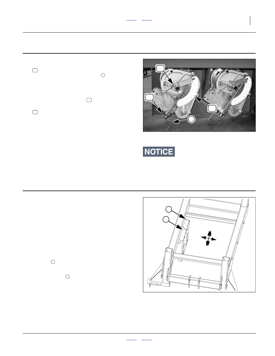
Prepare Meters
Refer to Figure 4
18. At a variable rate gearbox, remove the:
805-032C PIN HAIR COTTER .148 WIRE
then use the existing control crank
actuator to set
the indicator to 0 on the 0-100 scale. This prevents
the jackscrew from obscuring the scale.
Adjust the final crank handle position to fully down,
and re-insert the cotter pin
.
19. Remove and save the:
805-065C PIN WIRE RETAINING 1/4 X 1 3/4
This pin is re-used at step 41 to couple the new con-
trol arm to the gearbox control shaft.
Note: Removing this pin de-couples the gearbox control
shaft from the manual adjustment system. If it is
ever necessary to revert to manual control, move
the pin back to the manual arm.
20. Repeat step 18 and step 19 for the other meter.
Prepare ADC Driver Mounts
If your implement is an NTA607HD, NTA907HD,
NTA2007HD or NTA3007HD, continue at step 24 on
page 7.
On older ADC2350/B carts, the mounting holes for the
actuator driver modules may not be present, and must be
drilled. Newer ADC2350 carts, all NTA607/2007HD and
all NTA3007/907HD drills have holes present.
Refer to Figure 5
21. Locate the mounting holes on the ADC2350/B air
cart. These are 0.28x0.38in (7.1x95mm) slotted
holes 5.84in (14.8cm) apart.
One pair
is located on the forward break of the
gearbox mount plate.
The second pair
are located on the brace plate at
the center of the gearbox mount plate.
If these holes are present, continue at to step 24 on
page 7.
Equipment Damage Risk:
Never operate the meters with pins in both the manual/crank
arm and the linear actuator arm.
Figure 4
Existing (Manual) Meters
26306
3
50
52
51
52
52
51
Figure 5
ADC Driver Mounting Holes
29508
U
D
F
B
R
L
4
5
4
5