Create adc driver mounts, Adc front break holes, Dc brace plate holes – Great Plains VARIABLE RATE KIT Operator Manual User Manual
Page 6: Cb a d, Er v d, Ud l r
6
Air Drill Variable Rate Kit
Great Plains Mfg., Inc.
166-263M
6/23/2010
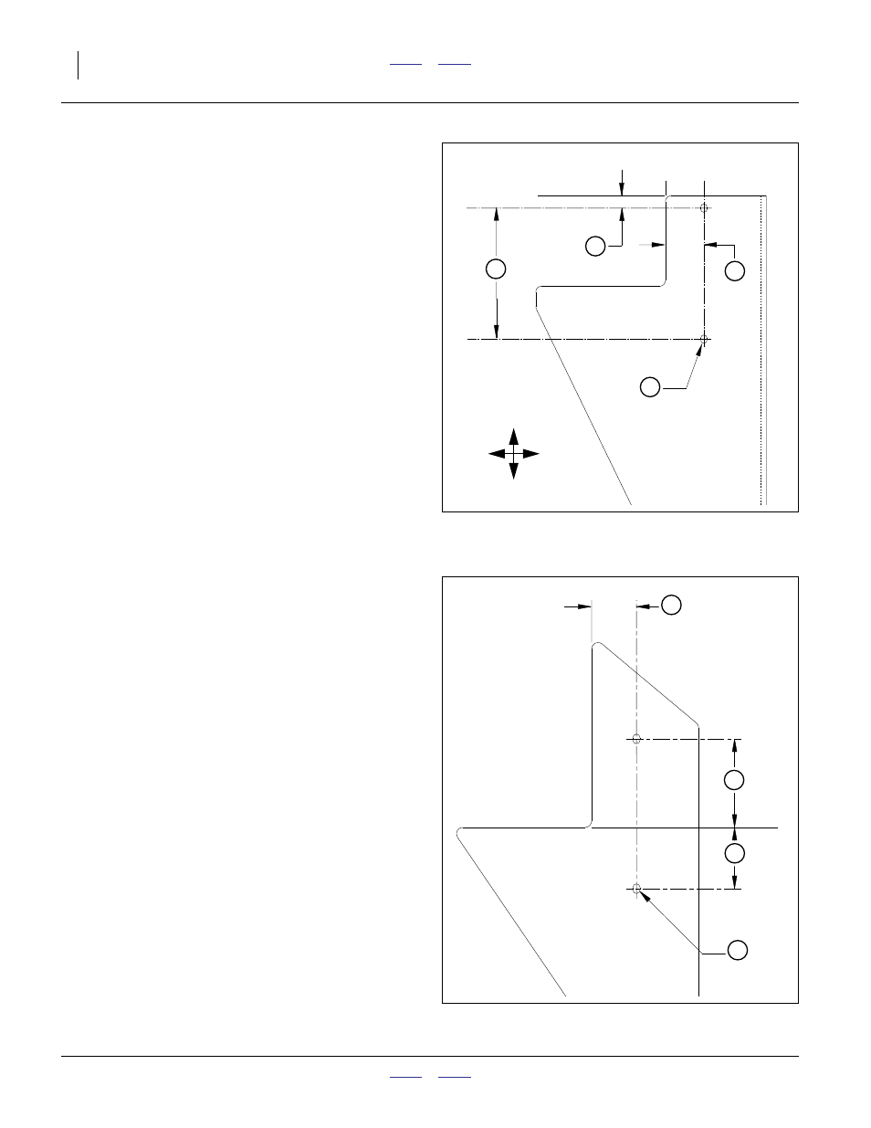
Create ADC Driver Mounts
ADC Front Break Holes
Refer to Figure 6
22. Drill and size two slotted holes in the front break of
the gearbox mount plate as follows:
If you are unable to make slotted holes, make two
circular holes 5.75 inches (14.6cm) apart.
DC Brace Plate Holes
Refer to Figure 7
23. Drill and size two slotted holes in the front break of
the gearbox mount plate as follows:
If you are unable to make slotted holes, make two
circular holes 5.75 inches (14.6cm) apart.
If you are unable to make two holes without per-
forming major disassembly of the gearbox struc-
tures, make only the top hole.
a
1
23
⁄
32
in
(1.72in)
(4.37cm)
Frame tool bar to
vertical slot center-lines
b
9
⁄
16
in
(0.55in)
(1.4cm)
Top slot center from
top of gearbox mount plate
c
5
27
⁄
32
in
(5.84in)
(14.8cm)
Slot to slot spacing,
center to center
d
9
⁄
32
x
3
⁄
8
in
(0.28 x 0.38in)
(7.1 x 95mm)
Two slots, dimensions are
horizontal x vertical
Figure 6
ADC Front Break Holes
29511
c
b
a
d
U
D
L
R
d
9
⁄
32
x
3
⁄
8
in
(0.28 x 0.38in)
(7.1 x 95mm)
Two slots, dimensions are
horizontal x vertical
e
1
3
⁄
4
in
(1.75in)
(4.4cm)
Frame tool bar to
vertical slot center-lines
r
2
25
⁄
64
in
(2.39in)
(6.1cm)
Bottom of frame tool bar to
upper slot center
v
3
29
⁄
64
in
(3.45in)
(8.8cm)
Bottom of frame tool bar to
lower center to center
r+v
5
27
⁄
64
in (5.84in)
(14.8cm)
Slot to slot spacing,
center to center
Figure 7
ADC Brace Plate Holes
29512
e
r
v
d