Connect driver leads – Great Plains VARIABLE RATE KIT Operator Manual User Manual
Page 13
Great Plains Mfg., Inc.
Installation Instructions
13
6/23/2010
166-263M
Connect Driver Leads
Refer to Figure 19
62. Connect the 2-pin lead
of the forward actuator
driver
to the 2-pin lead
of the forward linear
actuator
.
63. If two meters are being converted to variable rate,
connect the 2-pin lead
driver
to the 2-pin lead
actuator
Refer to Figure 19 and Figure 20
64. Locate the harness connection points already
present on the air cart or air drill. The cables have
labels near the 6-pin connectors, and have labels
identifying the connectors as:
ZEROMAX 1 and ZEROMAX 2, or
FRONT and REAR
65. Remove dust caps from the connectors. The caps
are not re-used. If the harness connector leads are
coiled up and tied, and need to be uncoiled to reach
the driver module leads, cut the cable tie.
66. Connect the 6-pin lead
of the forward actuator
driver
to the 6-pin FRONT or #1 harness lead
.
67. If two meters are being converted to variable rate,
connect the 6-pin lead
of the rear actuator
driver
to the 6-pin REAR or #2 harness lead
.
68. Select all new:
800-060C CABLE TIE .19X14.25 3DIA 50LB
Use four ties to secure the leads for each actuator
and driver. The NTA gearbox mount plate provides 6
0.21in (5.3mm) holes for this purpose.
Figure 19
Actuator Driver Leads
29498
1
3
2
39
20
1
2
39
1
2
39
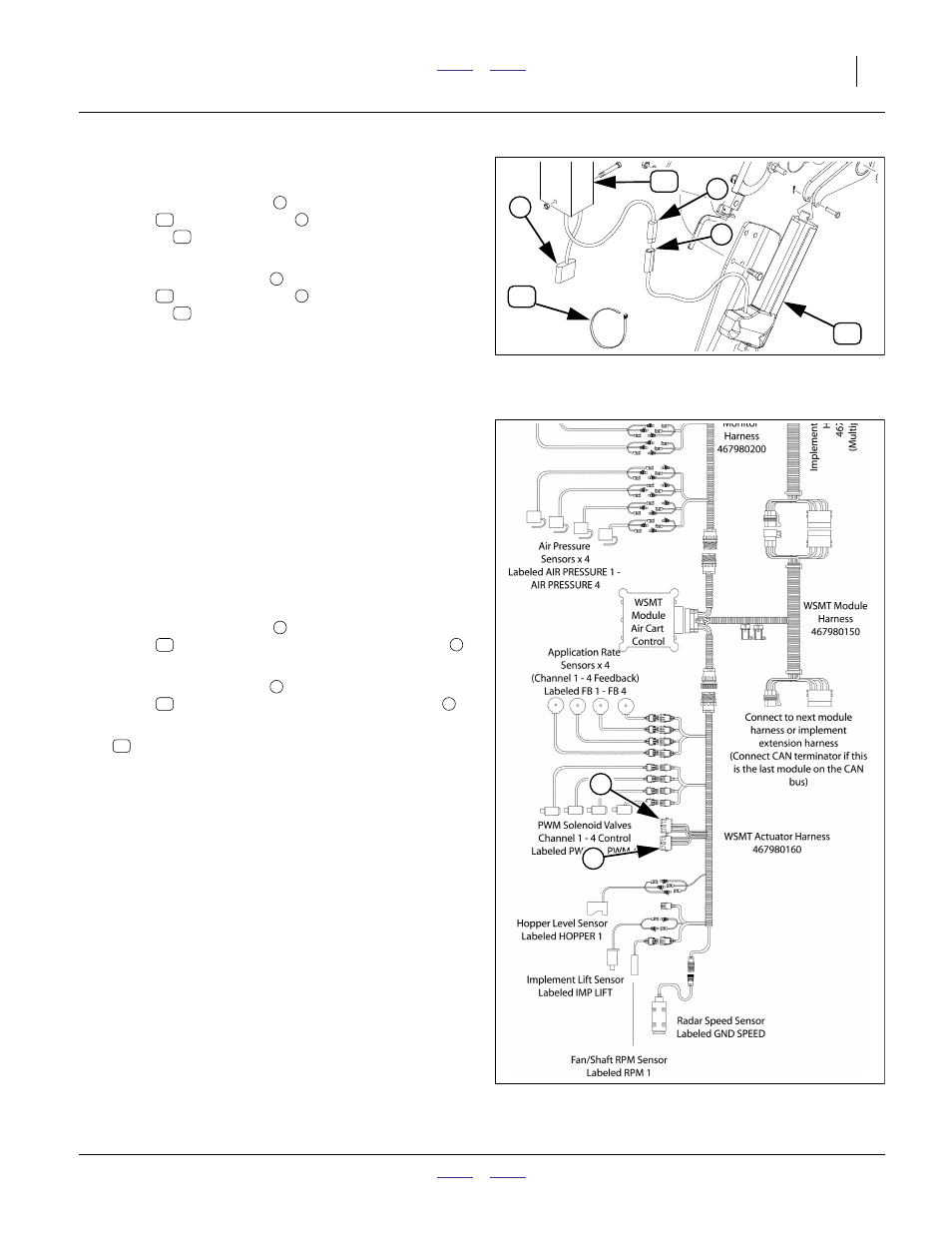
Figure 20
Harness Connection
29513
4
5
4
5
20