Lift-assist valve setup, Np3000 lift-assist valve, Install lift cylinder locks – Great Plains NP3000A Predelivery Manual User Manual
Page 30
26
NP3000
Great Plains Manufacturing, Inc.
407-613Q
03/31/2011
Lift-Assist Valve Setup
NP3000 Lift-Assist Valve
1.
The implement is presumed to be unfolded.
Hitch the implement to a tractor.
Raise the implement (as for parking).
2.
Locate the one-way restrictor valve
at the tee that
supplies the rear cylinder base ends.
3.
Turn the knob fully counterclockwise, then clockwise
one turn.
4.
Start a lift/fold operation. Initially, the lift occurs
before the fold. Stop. Lower.
5.
Turn the valve clockwise one turn.
6.
Start a lift/fold. Stop. Lower.
If the lift occurred before the fold, repeat step 5.
If the fold occurred before the lift, back the valve off
(counterclockwise) a partial turn, and re-test lift/fold.
7.
Find the point at which the wings fold to the wing
locks prior to lift commencing.
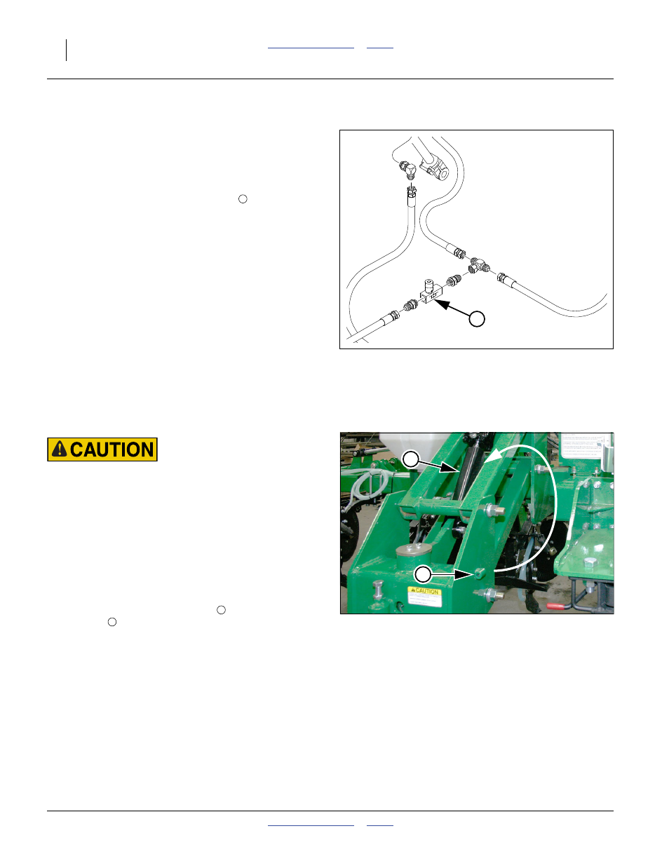
Install Lift Cylinder Locks
Falling Hazard:
Do not climb or stand on tires or wheels. Even at full extension
on level ground, tires may not be in firm ground contact. They
could spin without warning. A fall could result in serious
injury.
Refer to Figure 39
Transport locks are present on all wheel assemblies with
hydraulic cylinders. To install cylinder stops:
1.
Fully raise implement. Set lift circuit to Neutral.
2.
At each rear lift-assist cylinder, remove cotter pin and
lock pin. Remove lock channel
from storage
location
.
Figure 38
Lift-Assist Valve
31612
1
1
3
1
ll
Figure 39
Rear Lift Cylinder Lock Channel
31619
1
3