Install lift-assist casters – Great Plains NP3000A Predelivery Manual User Manual
Page 21
Great Plains Manufacturing, Inc.
Install Components
17
03/31/2011
407-613Q
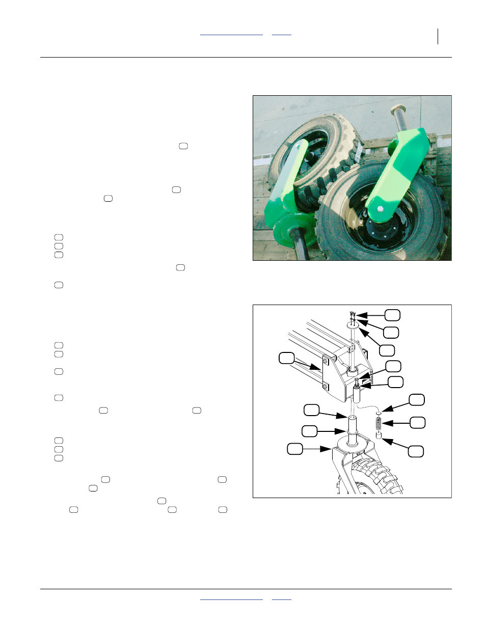
Install Lift-Assist Casters
If the rear lift-assist casters are already installed, con-
tinue at “Install Transport Rest” on page 18.
For this component, two lifters, or a single lifter and a set
of tall supports are required. Plan the installation based
on the available tools. These instructions assume a sin-
gle lifter and supports. The caster yoke
can be lifted
by strapping a lifter fork under the yoke.
1.
Disconnect the rod ends of both lift-assist cylinders.
Refer to Figure 24
2.
Loosen caster stabilizer jam nuts
. Back the
adjuster bolts
most of the way out. Secure with
jam nut finger-tight.
3.
Locate two sets of the caster stabilizer internal com-
ponents:
266-012D PLATE RND 3/16" THK 1 7/8" DIA
807-143C SPRING COMP 1.88OD x .362W
266-020D UHMW RND 2.0 DIA X 2.0 LONG
4.
Hoist one of the caster weldments
high enough
that the caster yoke assembly
407-317L CASTER LOCKUP ASSEMBLY
can be positioned under it.
Install supports at the parallel arms or secure the
hoist.
5.
On one of the caster yokes, remove and save two
sets of:
802-034C HHCS 1/2-13X1 1/4 GR5
804-015C WASHER LOCK SPRING 1/2 PLT
and one:
161-231D NTA CASTER RETAINER CAP
Do not remove the:
804-102C PIVOT THRUST WASHER
6.
Lift the yoke
. Align the vertical shaft
with the
pivot. Raise the yoke one or two inches into the pivot.
7.
Insert into the stabilizer tube, in this order, one each:
266-012D PLATE RND 3/16" THK 1 7/8" DIA
807-143C SPRING COMP 1.88OD x .362W
266-020D UHMW RND 2.0 DIA X 2.0 LONG
8.
Fully raise the yoke into the caster weldment. Secure
with one cap
, and two sets of lock washers
and bolts
.
9.
Loosen the stabilizer jam nut
. Turn the adjuster
bolt
until it contacts the plate
and spring
.
Tighten one more inch. Secure jam nut.
10. Repeat step 4 through step 9 for the other caster.
11. Re-connect the lift-assist cylinders.
ll
Figure 23
Caster Yokes on Trailer
31703
18
41
33
13
52
14
16
18
Figure 24
Lift-Assist Caster
31701
18
13
52
14
31
43
12
46
16
33
41
21
31
43
12
46
18
21
13
52
14
12
43
31
41
33
13
52