Install sub-frame, Prepare frames, Attach sub-frame – Great Plains NP3000A Predelivery Manual User Manual
Page 14: Install sub-frame prepare frames attach sub-frame
407-613Q
03/31/2011
10
NP3000
Great Plains Manufacturing, Inc.
Install Sub-Frame
If the implement was ordered without on-board fertilizer
tanks, the smaller tankless sub-frame is already
installed. Continue at “Prepare Hydraulics” on page 14.
Loss of Time Risk:
Install in order. To ensure safety and reduce effort, the topics
must be completed in the order presented. Later topics rely on
earlier topics having been completed. Some steps cannot be
performed at all if required prior steps are not yet completed.
The tank sub-frame must be attached prior to hydraulic
work, because the weight-transfer controls must be dis-
connected from hoses and reconnected to route them
through the tank sub-frame.
Prepare Frames
1.
Support the main frame so that it cannot tip back-
ward while having the sub-frame pushed against it.
Clear the front tool bar of any hoses or harnesses
that might be pinched during frame attachment.
Refer to Figure 10 (which, for clarity, omits tanks and other
hardware already installed on both frames)
2.
Select eight:
806-128C U-BOLT 3/4-10 X 6 1/32 X 5 5/8
and 16 sets:
804-023C WASHER LOCK SPRING 3/4 PLT
803-027C NUT HEX 3/4-10 PLT
These may be on the mainframe, or loosely installed
in the sub-frame mounting plate holes. Remove the
nuts
and washers
. Place the U-bolts
on the
mainframe at the approximate mounting locations.
Refer to Figure 11
3.
Use a hoist or fork lift to move the sub-frame to the
main frame. If using a fork lift, as shown, approach
the sub-frame from the front (hitch) side. Keep lifting
tines clear of plumbing. Make sure the sub-frame is
completely level, and centered on the main frame.
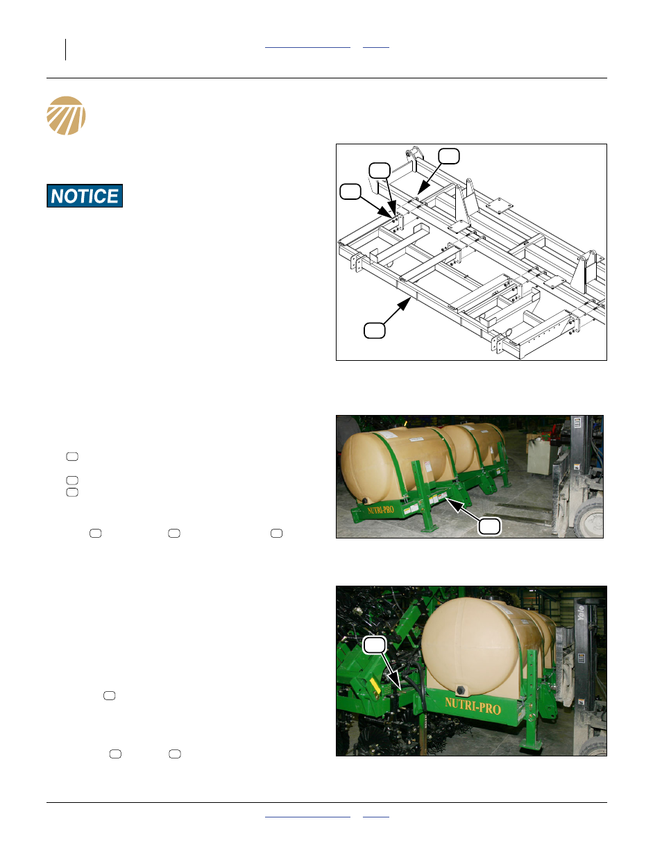
Attach Sub-Frame
Refer to Figure 12
4.
Carefully bring the sub-frame into alignment with the
U-bolts
.
5.
Check that the sub-frame is centered on the main
frame (left to right).
6.
Secure the sub-frame on the U-bolts with lock
washers
and nuts
. Tighten to Grade 5 torque
specification.
Figure 10
Tank Sub-Frame Mounting
32034
51
45
39
26
Figure 11
Approaching Sub-Frame
32035
26
51
45
39
39
45
51
Figure 12
Aligning Sub-Frame
32036
51
51
45
39