Dismount transport rest, Install transport rest, Dismount transport rest install transport rest – Great Plains NP3000A Predelivery Manual User Manual
Page 23
Great Plains Manufacturing, Inc.
Install Components
19
03/31/2011
407-613Q
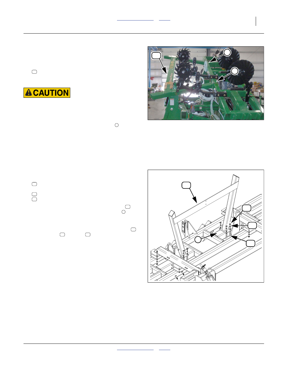
Dismount Transport Rest
Refer to Figure 26 and Figure 27 (depicting wings still folded)
18. With the wings unfolded, attach hoist lines at each
end of the cross plate of the:
407-478H NP40 WING REST
Loop them around both the riser tubes below and the
plate to keep them from slipping.
Sharp Object Hazards:
Keep feet and legs clear of discs. This dismount requires work-
ing in between row implements. Discs are sharp and can cause
injury.
19. Loosen the nuts on the shipping U-bolts
that the hoist is supporting the full weight of the free
end of the rest.
20. Have workers support the base ends of the rest
while removing the U-bolts completely.
Install Transport Rest
Refer to Figure 27
21. Select two:
806-039C U-BOLT 5/8-11 X 6 1/32 X 7 3/4
and eight sets:
803-021C NUT HEX 5/8-11 PLT
804-022C WASHER LOCK SPRING 5/8 PLT
22. With the cross plate to the rear, hoist the rest
to
implement center, over the middle tool bars
of the
mainframe.
23. Check that the rest’s base plates are equal distances
from implement center-line. Secure with U-bolts
,
lock washers
and nuts
Do not install the SMV reflector until “Install SMV
Reflector” on page 22.
Note: The removed U-bolts are used only for shipping,
and are returned to Great Plains. The transport
rest is installed with different U-bolts.
Figure 26
Transport Rest in Over-Fold
31709
24
5
24
5
Figure 27
Transport Rest
31025
24
6
38
44
49
49
38
44
24
6
49
44
38