Install t-banders – Great Plains Smartbox Mount Kit Yield Pro Planters User Manual
Page 15
Great Plains Mfg., Inc.
Installation Instructions
15
12/12/2006
403-206M
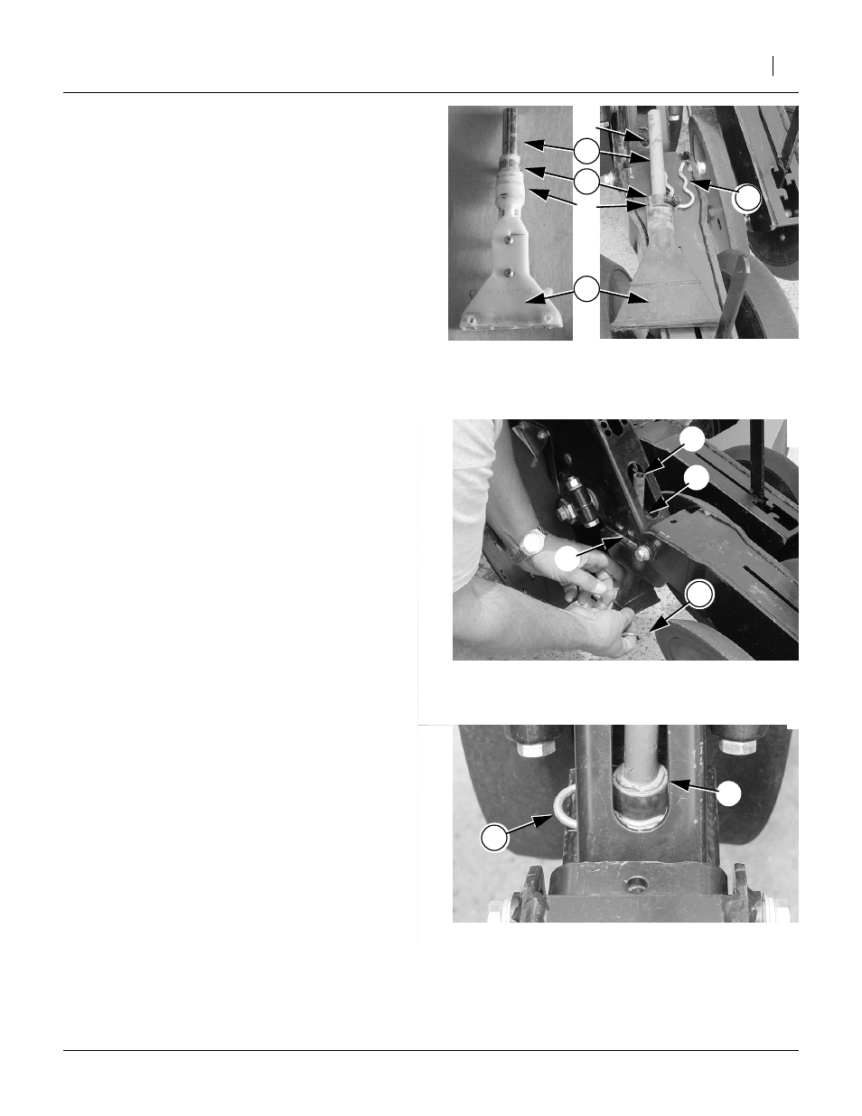
Install T-Banders
Refer to Figure 24, which depicts two variations of T-bander
The T-Bander (39) is the distribution nozzle for the
Smartbox system. It mounts under the row unit, through
a dedicated pair of holes
➀
at the hinge point between
the opener and the press wheel assembly.
The T-Bander assembly consists of four parts:
(39) 817-655C (T-BANDER)
(12) 116-001D (T-BANDER TUBE)
(22) 800-126C (CLAMP WRM DRV #5 SS (.44-.70))
(34) 805-185C (PIN COTTER .186 WIRE DIA)
If your application requires a longer nozzle on the T-
bander, an extension boot is available as Great Plains
part number 816-511C.
Repeat Step 55 through Step 58 for each row unit
served by a Smartbox meter.
Refer to Figure 24 and Figure 25
55. Attach T-Bander tube (12) to T-Bander (39).
Slide either end of tube fully down over neck of T-
Bander.
Note grooves
➃
for cotter pin, but do not attach
cotter pin at this time.
56. Place clamp (22) over neck of T-Bander, and posi-
tion above groove
➃
. Tighten clamp.
57. Insert T-Bander assembly
➀
through holes
➁
from
beneath row unit. Align it so that the exit port is
side-to-side.
58. Insert cotter pin (34) in slot
➂
so that it engages
grooves
➃
on T-Bander. If your T-bander has multi-
ple grooves for the cotter pin, consult AMVAC for a
height recommendation.
25330
Figure 24
T-Bander w/Tube Attached
24178
➀
➃
Figure 25
Insert T-Bander
24180
➁
➂
➀
Figure 26
T-Bander w/Cotter Pin
24181
➀