Al- circuit board, F, -j or -g wiring harness – SARGENT AL - Alarmed Exit User Manual
Page 3
3
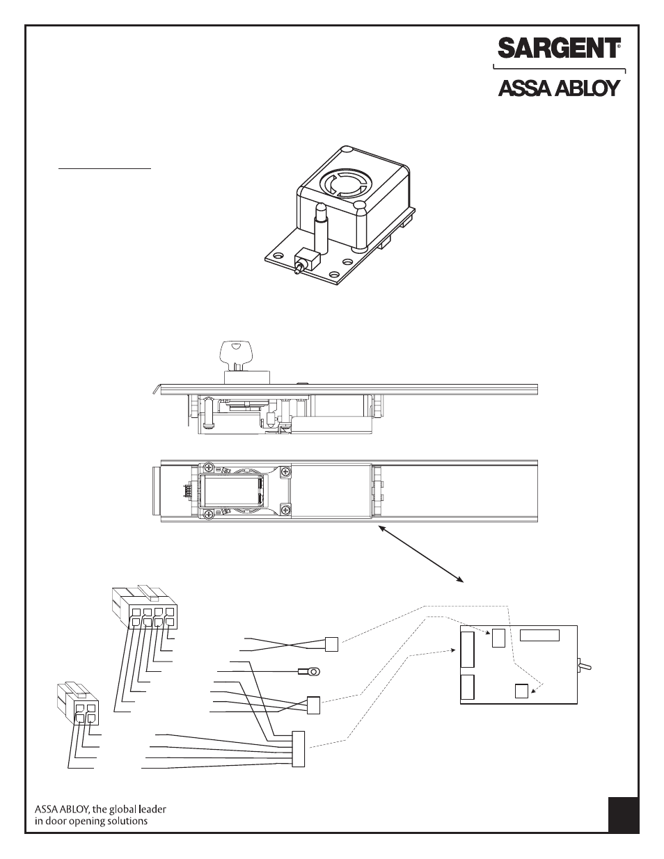
F. Dip Switch (SW-2, 6-position)
Factory settings shown. Refer to instruction A7724B for field selectable settings.
1. DS-1 = OFF, DS-2 = OFF - REX / Passage Delay (set to 7 seconds)
2. DS-3 = OFF, DS-4 = OFF - Automatic Alarm Reset (set to 2 minutes)
3. DS-5 = ON - Selects LED color (Armed = Green, Violation = Red, Passage = Yellow)
4. DS-6 = ON - Monitor Relay is enabled (will activate when rail is violated)
G. AL- Circuit Board and 546 Harness
Printed Circuit Board
Note: SW-1, Arm/Disarm Switch
shown in ON (armed) position
AL- Circuit Board
J2-3 & 4 to
Rail Switch
J2-1 (+), J2-2 (-)
to Battery
SW-1
Arm/Disarm
Switch
4
2
3
1
1, Violet (DS)
2, Grey (DS)
4, Tan (RR)
3, Pink (RR)
1
7
5
6 4
3
2
8
1, Black (RP, -9v)
2, Red (RP, +9v)
3, White (Rex)
5, Orange (Rex)
7, Brown (RM - NO)
8, Yellow (RM - NC)
6, Blue (RM - C)
4, Green (EG)
Connect to
rail mounting
bracket
1
1
1
SW-2
6-position
dip switch
J3
1
1
1
1
J2
J4
J1
1
6 5
2
4 3
ON
OFF
The 546 Wiring Harness connects to
the AL- Circuit Board as shown
546-F, -J or -G
Wiring Harness
AL-Insert with circuit board
A7251C
Copyright © 2004, 2006, 2008, 2009, 2012, Sargent Manufacturing Company, an ASSA ABLOY Group company. All rights reserved.
Reproduction in whole or in part without the express written permission of Sargent Manufacturing Company is prohibited.