SARGENT AL - Alarmed Exit User Manual
Connector system
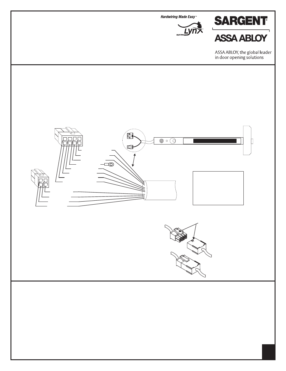
A7251C
1
C. Connector System Notes:
The system is designed to be installation friendly with
pluggable connectors from the electric hinge through the door
to the rail. The only wiring required is to the loose wires on the
pigtail harness assembly on the frame side of the electric hinge
IMPORTANT:
The plug and receptacle connectors are designed to mate
and lock together as shown in the figure. Plug the connectors
into each other with the locking mechanism aligned as indicated
Do NOT force connectors on any other way.
A. General
These instructions cover installing and wiring remote options to the AL- 80 Series Alarmed Exit Device using the 546
wiring harness. Refer to instruction A7224B for additional instructions. Remote options include Remote Power, Remote
Monitor, Request to Exit (REX), Door Status and Remote Reset. In addition, there are field selectable options:
REX/Passage Time Delay, Automatic Alarm Reset and Remote Monitor Relay Enable/Disable
B. Important
1. Caution: Disconnect all input power before beginning installation to prevent electrical shock and
equipment damage
2. Installer must be a trained, experienced service person
3. All wiring must comply with applicable local electrical codes, ordinances and regulations
Instructions for Installation and Wiring Remote Options
to AL- Prefix 80 Series Alarmed Exit
Devices
using the 546 Wiring Harness to ElectroLynx™ Connector System
For assistance, contact SARGENT at 800-810-WIRE (9473) or www.sargentlock.com
D. Installation Notes
1. With new applications, a raceway harness with 8 & 4-pin connectors will be pre-installed inside the door by ASSA ABLOY
door manufacturers when specified during the ordering process. Raceway harness kits are also available for retrofit
applications. For retrofit applications, refer to retrofit instructions
2. If door does not have a raceway harness with connectors, either consult factory for raceway retrofit kit or cut the
connectors off product and hard wire as required
3. Wiring to pigtail harness is per facility wiring requirement. The rail, raceway, electric hinge and pigtail connector
terminations and wire colors all match
AL- 80 Series Rail
4 2
3 1
1, Violet (DS)
2, Grey (DS)
4, Tan (RR)
3, Pink (RR)
1
7 5
6 4
3
2
8
1, Black (RP, -9v)
2, Red (RP, +9v)
3, White (Rex)
5, Orange (Rex)
7, Brown (RM - NO)
8, Yellow (RM - NC)
6, Blue (RM - C)
4, Green (EG)
546-F, -J or -G harness
with 8 and 4-pin connectors
RP - Remote Power
Rex - Request to Exit
EG - Earth Ground
RM - Remote Monitior
DS - Door Status
RR - Remote Reset
Locking mechanism
Plug
Receptacle
Instructions for Installation and Wiring
Remote Options to SARGENT AL-Prefix 80
Series Alarmed Exit Devices using the 546
Wiring Harness to ElectroLynx
®
Connector
System
FOR ASSISTANCE CONTACT SARGENT AT 800-810-WIRE (9473) or www.sargentlock.com
Copyright © 2004, 2006, 2008, 2009, 2012, Sargent Manufacturing Company, an ASSA ABLOY Group company. All rights reserved.
Reproduction in whole or in part without the express written permission of Sargent Manufacturing Company is prohibited.